What is an induction motor and how does it work
The induction motor is simple and reliable and this is why it is very often used in production and in household appliances, from the valve drive to the rotation of the drum in the washing machine. In this article, in simple words, we will talk about what are asynchronous electric motors, what is it and how does this type of electric machine work.
Views
Induction motors (AM) are divided into two main groups:
- squirrel cage rotor
- with a phase rotor.
If we omit the nuances, the difference is that the squirrel-cage rotor motor does not have brushes and pronounced windings, it is less demanding in maintenance. Whereas in asynchronous motors with a phase rotor there are three windings connected to slip rings, the current from which is removed by brushes. Unlike the previous one, it is better to control the torque on the shaft and it is easier to realize a smooth start to reduce inrush currents.
The rest of the engines classify:
- by the number of supply phases - single-phase and two-phase (used in everyday life when powered by a 220V network), and three-phase (most widely used in production and in workshops).
- by way of fastening - flange or on paws.
- by operation mode - for a long, short-term or repeatedly-short-term mode.
And a number of other factors that affect the choice of a particular product for use in specific conditions.
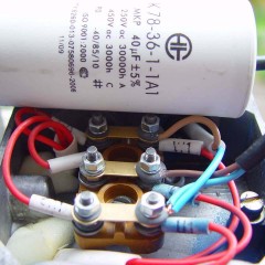
A lot can be said about single-phase electric motors: some of them are launched through a capacitor, and some require a starting and working capacity. There are also options with a short-circuited turn, which work without a capacitor and are used, for example, in hoods. If you are interested, write in the comments and we will write an article about it.
Device
By definition, “asynchronous” refers to an AC motor in which the rotor rotates more slowly than the magnetic field of the stator, that is, asynchronously. But this definition is not too informative. To understand it, you need to figure out how this engine is designed.
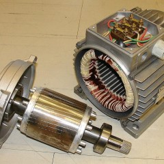
An induction motor, like any other, consists of two main parts - rotor and stator. “For Dummies” in electrics we decipher:
- The stator is called the fixed part of any generator or electric motor.
- The rotor is called the rotating part of the engine, which drives the mechanisms.

The stator consists of a housing, the ends of which are closed by bearing shields in which the bearings are installed. Depending on the purpose and power of the engine, sliding or rolling bearings are used. The core is located in the case, a winding is installed on it. It is called a stator winding.

Since the current is alternating to reduce losses due to stray currents (Foucault currents) the stator core is drawn from thin steel plates isolated from each other by scale and bonded with varnish.A supply voltage is supplied to the stator windings, the current flowing in them is called the stator current.
The number of windings depends on the number of supply phases and the design of the motor. So a three-phase motor has at least three windings connected by a star or triangle circuit. Their number may be greater, and it affects the speed of rotation of the shaft, but we will talk about this later.
But with the rotor, things are more interesting, as already mentioned, it can be either short-circuited or phase.

A squirrel-cage rotor is a set of metal rods (usually aluminum or copper), in the figure above they are indicated by the number 2, soldered or filled into the core (1), closed by rings (3). This design resembles a wheel in which domesticated rodents run, which is why it is often called the “squirrel cage” or “squirrel wheel” and this name is not slang, but quite literary. To reduce the higher harmonics of the EMF and pulsation of the magnetic field, the rods are laid not along the shaft, but at a certain angle relative to the axis of rotation.
The phase rotor differs from the previous one in that it already has three windings, as on a stator. The beginning of the windings are connected to the rings, usually copper, they are pressed onto the motor shaft. Later we will briefly explain why they are needed.

In both cases, one of the ends of the shaft is connected to a mechanism driven by movement, it is conical or cylindrical in shape with or without grooves to install a flange, a pulley and other mechanical drive parts.
An impeller, which is necessary for blowing and cooling, is fixed on the “rear” part of the shaft; Thus, cold air is directed along the edges of the induction motor, if for some reason this impeller does not rotate, it will overheat.

The design of the first induction motor was developed by M.O. Dolivo-Dobrovolsky and he patented it in 1889. Without any changes, it has survived to the present.
Principle of operation
Asynchronous electric machines are often called induction, this is due to their principle of operation. Any electric motor is driven into rotation as a result of the interaction of the magnetic fields of the rotor and stator, as well as due to the Ampere force. A magnetic field, in turn, can exist either around a permanent magnet, or around a conductor through which current flows. But how exactly does an asynchronous machine work?
In an induction motor, unlike others, there is no excitation winding per se, whereas does it have a magnetic field? The answer is simple: an induction motor is a transformer.
Consider the principle of its operation on the example of a three-phase machine, since it is they that are found more often than others.
In the figure below you see the location of the windings on the stator core of a three-phase asynchronous motor.

As a result of the flow of a three-phase current, a rotating magnetic field appears in the stator windings. Due to the phase shift, the current flows either one or the other winding, in accordance with this there is a magnetic field, the poles of which are directed according to the rule of the right hand. And in accordance with the change in current in one or another winding, the poles are sent in the corresponding direction. As the following animation illustrates:

In the simplest (two-pole) case, the windings are stacked in such a way that each of them is offset by 120 degrees relative to the previous one, as is the phase angle of the voltage in the AC network.
The rotation speed of the stator magnetic field is called synchronous. Learn more about how it rotates and why you will learn from the next video. Note that in two-phase (capacitor) and single-phase motors - it is not rotating, but elliptical or pulsating, and the windings are not 3, but 2.
If we consider an asynchronous motor with a squirrel-cage rotor, the magnetic field of the stator induces an EMF in its rods, since they are closed, then current flows.Because of this, a magnetic field also occurs.
As a result of the interaction of two fields and Ampere forceacting on the rotor, it begins to rotate after the rotating stator magnetic field, but at the same time always lagging slightly behind the rotational speed of the stator MP, this lag is called slip.
If the rotation speed of the magnetic field is called synchronous, then the rotation speed of the rotor is already asynchronous, from which he received this name.
In AD with a phase rotor, things are similar, except that a rheostat is connected to its rings, which, after the engine enters the operating mode, is removed from the circuit and the windings are short-circuited. This is shown in the diagram below, but instead of a rheostat, constant resistors are used, connected or shunted by KM3, KM2, KM1 contactors.
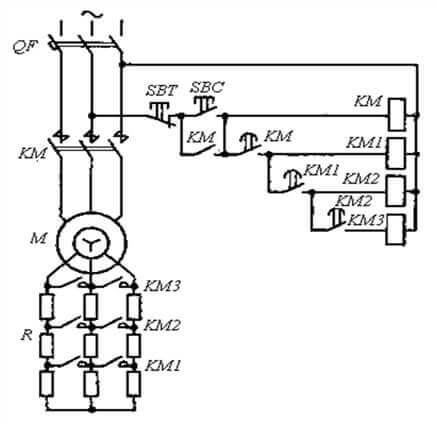
This approach allows for a smooth start and reduce inrush currents, by increasing the active electrical resistance of the rotor.
 To summarize:
- The current in the stator windings generates a magnetic field.
- The magnetic field leads to current in the rotor.
- The current in the rotor causes a field to appear around it.
- Since the stator field rotates, because of its field, the rotor begins to rotate behind it.
Slip and rotation speed
The rotation frequency of the stator magnetic field (n1) is greater than the rotation frequency of the rotor (n2). The difference between them is called slip, and is denoted by the Latin letter S and calculated by the formula:
S = (n1-n2) * 100% / n1
Sliding is not a drawback of this electric motor, because if its shaft rotated with the same frequency as the stator magnetic field (synchronously), then no current would be induced in its rods, and it would simply not rotate.
Now about a more important concept - the rotational speed of the rotor of an induction motor. It depends on 3 values:
- supply voltage frequency (f);
- the number of pairs of magnetic poles (p);
- slip (S).
The number of pairs of magnetic poles determines the synchronous speed of rotation of the field and depends on the number of stator windings. Sliding depends on the load and design of a particular electric motor and lies in the range of 3-10%, that is, asynchronous speed is very slightly less than synchronous. Well, the frequency of the alternating current is fixed at 50 Hz.
Therefore, the rotational speed of the shaft of an induction motor is difficult to regulate, you can only affect the frequency of the mains, that is, by setting a frequency converter. It is possible to lower the stator voltage, but then the power on the shaft decreases, nevertheless, such a technique is used when starting the AM with switching the windings from star to delta to reduce inrush currents.
The frequency of rotation of the stator field (synchronous speed) is determined by the formula:
n = 60 * f / p
So in an engine with one pair of magnetic poles (two poles) the synchronous speed is:
60 * 50/1 = 3000 rpm
The most common options for electric motors with:
- one pair of poles (3000 rpm);
- two (1500 rpm);
- three (1000 rpm);
- four (750 rpm).
The actual rotor speed will be slightly lower, on a real induction motor it is indicated on the nameplate, for example, here - 2730 rpm. Despite this, the people will call such an asynchronous motor according to synchronous speed or simply “three thousand meters”.

Then its slip equals:
3000-2730*100%/3000=9%
Scope of application
Asynchronous electric motor has found application in all areas of human activity. Those that are powered from one phase (from 220V) can be found in actuators of low power or in household appliances and tools, for example:
- in a washing machine of the "baby" type and other old Soviet models;
- in a concrete mixer;
- in the fan;
- in the hood;
- and even in lawn mowers of the upper price segment.


In production in three-phase networks:
- automatic gate valves;
- hoisting mechanisms (cranes and winches);
- ventilation;
- compressors;
- Pumps
- wood and metalworking machines and more.


AD is also used in electric vehicles, and recently the asynchronous motor with a Slavyanka type winding and the so-called Duyunov motor-wheel are actively advertised on the Internet, which you can find out from the developer’s video.
The scope of asynchronous motors is so vast that the list alone will be longer than this article, so every electrician should know how it is arranged, what it is for and where it is used. To summarize and list the pros and cons of these devices.
Pros:
- Simple construction.
- Low cost.
- Almost no maintenance.
The main disadvantage is the difficulty in adjusting the speed compared to the same DC motors or universal collector machines. Accordingly, it is difficult to organize smooth start-up of large machines, and more often this is done using an expensive frequency converter.
This is where we end with the consideration of induction motors and their scope. We hope that after reading the article you will understand what it is and how this electric machine works!
Related materials: