What are the types of electric motors and how do they differ
How engines work
The principle of operation of all types of electric motors consists in the interaction of the magnetic fields of the rotor and stator. In this case, the magnetic field can be created by a constant magnetic or winding (coil-electromagnet).

Depending on the power and type of motor, the windings can only be located on the stator or on the stator and on the rotor. Let's try to explain the device and the principle of operation for dummies in electrics.
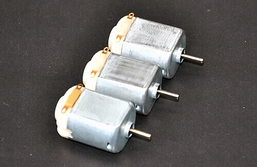
To begin with, we consider the design of collector motors. For example, in small DC collector motors, as for radio models, permanent magnets are located on the stator, and coils of copper wire are wound in the rotor. The current to the rotor coils of such an electric motor is supplied through a brush assembly consisting of brushes and a collector. On the collector are lamellas, to which the leads of the windings are attached.

After turning on the power, the rotor (anchor) begins to rotate, the collector is fixed on it, and the fixed brushes touch alternately different pairs of collector lamellas. Through brushes and lamellas, current is supplied to the rotor windings either to one winding or to another, thus creating a changing magnetic field that interacts with the magnet field. As a result, the poles of the rotating and stationary electromagnets are attracted, which is why rotation occurs.
If we omit some nuances, then the greater the current of the rotor, the larger this field and the faster the rotor rotates. However, this is mainly applicable to DC and AC collector machines (they are universal).
If we talk about an asynchronous motor (HELL) with a squirrel-cage rotor - this is an AC electric motor without brushes. In it, the windings are located on the stator (a), and the rotor is a rod (b), shortly closed by rings - the so-called squirrel cage.

In this case, the rotating magnetic field of the stator generates a current in the rods of the rotor, due to which another magnetic field also appears. And what happens when two magnets are located nearby?
They are repelled or attracted to each other. Since the rotor is fixed at the ends in the bearings, the rotor begins to rotate.AM is intended only for alternating current, and the shaft rotation speed depends on the frequency of the current and the number of poles in the stator windings, we will discuss this issue in more detail in the article on asynchronous motors.
But to start the rotation of the shaft of such an engine, it is important either to push it (to give the initial speed), or to create a rotating magnetic field. It is created using windings arranged in a certain way, connected to a three-phase power supply network (for example, 380V), or using starting and working capacitors (in so-called capacitor induction motors).
In addition to the interaction of magnetic fields in the rotation of the motor shaft is involved and Ampere force.

Therefore, you need to understand that the moment on the shaft of the abstract engine and the number of revolutions depend on the design and type of the electric machine, as well as on the strength of the current and its frequency. I repeat that in this article we will not go into details about the features of the devices of each of the types and types of electric motors, but we will make separate articles for this.

It should be noted that asynchronous and universal collector motors are most common in everyday life and in production, in the drives of construction vehicles. They are used everywhere, both for the movement of industrial mechanisms, and for cars, electric vehicles and used in household appliances, up to an electric toothbrush.
Main classification
So, electric motors are mainly divided into machines operating on direct current, as well as on alternating current. What is the difference between alternating current and direct current, we said in the article: https://my.electricianexp.com/en/chem-otlichaetsya-peremennyj-tok-ot-postoyannogo.html. We will consider types of electric motors from machines working from a break.
AC motors
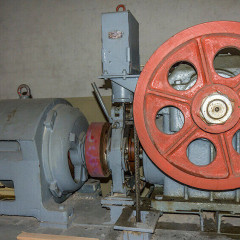
Most of the electric machines used in production and in everyday life, to drive elevators, in other types of electric drives operate from AC.
AC motors can be classified as follows:
- asynchronous;
- synchronous.
In this case, induction motors are distinguished either by the design of the rotor:
- squirrel cage rotor (most common with any number of phases);
- with a phase rotor (only three-phase).
And by the number of phases:
- single-phase (with a starting capacitor) are used in household electric fans and other low-power devices;
- condenser or two-phase (it is single-phase with a capacitor that does not turn off during operation, due to which a "second" phase is created) are used in small pumps, ventilation, on "baby" type washing machines and old models made in the USSR;
- three-phase are most common and are used everywhere in production.
There are different designs of single-phase blood pressure, the list shows two main options!
A feature of all asynchronous electric motors is that the rotor speed is slightly less than the rotation speed of the stator magnetic field and is equal to:

where n is the number of revolutions per minute, f is the frequency of the supply network, p is the number of pole pairs, s is gliding, and "60" is seconds per minute.
Thus, the rotor speed is determined by the frequency of the supply network, the design of the windings, or rather the number of pairs of poles (coils) in it and the magnitude of the slip.
Sliding is a value that characterizes how much less is the rotor speed relative to the frequency of a rotating magnetic field. Under normal operating conditions lies in the range of 0.01-0.06. In simple terms, the field in the stator with one pair of poles rotates with speed:
60 * 50/1 = 3000 rpm
With two pairs - 1500 rpm, and with three pairs - 1000 rpm.
When sliding, for example, at 0.05, the rotor speed will be equal to:
3000 * (1-0.05) = 2850 rpm
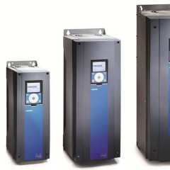
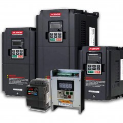
To adjust the speed of such motors use frequency converters, since we cannot affect the other variables of the above formula.
The most common are asynchronous motors with a supply voltage of 220V for connecting the windings according to the triangle circuit and 380V according to the star circuit.

If in a three-phase electric machine the rotating stator field is created by the location of the windings and the phase shift in the network by 120˚, then this effect is not observed in single-phase ones. The shaft will rotate if you set it to the initial rotation by turning the shaft by hand or by installing a phase-shifting capacitor, which will create a phase shift on the starting winding.

Two-phase capacitor motors are arranged in a similar way, but the second winding does not turn off after starting, but continues to work through capacitor. Therefore, the name "two-phase" rather refers to the design and wiring diagram, rather than to power circuits. Both two-phase and single-phase are designed to operate on a 220V network.

Synchronous electric motors (LEDs) are almost always carried out with an excitation winding at the armature, and the excitation current is transmitted to it either through the brush assembly or induced by an electromagnetic system.

This is necessary so that its shaft rotates with a frequency that coincides with the frequency of rotation of the stator field. That is, there is no such parameter as slip in this case.

The excitation current is supplied from special excitation systems, such as a "generator-motor" or electronic converters on thyristors or transistors. The most common at domestic enterprises are such devices as VTE, TVU, etc.

There is not always a field winding and brushes, for example, in a microwave oven, a permanent magnet synchronous motor is used in the plate rotation drive.
Synchronous machines are explicit and implicit. The visual differences are in the design of the rotor, in practice there is a difference in their characteristics, methods of production and design. In practice, an ordinary home electrician is unlikely to encounter them.

It remains to say the main thing about AC motors - they are difficult to adjust the rotation speed due to the fact that their speed is tied to speed. A decrease in voltage (current) on the stator or excitation (for synchronous and asynchronous with a phase rotor) leads to a drop in torque and an increase in the slip value (for HELL), while the shaft can rotate more slowly. To regulate the speed of such engines, you need a frequency converter. About how to choose a chastotnik, we told in the article: https://my.electricianexp.com/en/vybor-chastotnogo-preobrazovatelya.html.
DC Motors
The following types and types of DC motors are available:
- DC Brush Motors They consist of magnets or an excitation coil and an armature; current to the armature winding is transmitted using a brush assembly, the drawback of which is gradual wear.
- Universal collector motors. They are similar to the previous ones, but can work both from direct and from alternating current.
- Brushless or brushless. It consists of stator windings, permanent magnets are installed on the rotor. It is connected to the DC circuit through a special controller that switches the stator windings.

Collector motors can be divided into groups according to the type of excitation:
- with self-excitation;
- with independent arousal.
According to the type of connection of the field windings, they are distinguished as follows:
- Sequential excitation allows you to get a high moment on the shaft, but the idle speed is also very high and can damage the engine (will go into the spacing).
- Parallel excitation - in this case, the revolutions are more stable and do not change under load, but the torque on the shaft is less.
- Mixed excitement combines the advantages of both types.
In low-power collector DCTs, excitation is most often organized using permanent magnets.

With independent excitation of the collector electric motor, the stator and rotor windings are not connected to each other, but in essence they are powered from different sources.Thus, it is possible to organize the adjustment of the moment or speed, as well as to achieve greater energy efficiency.
Depending on the design, such an electric motor can work either only from direct current, or work from alternating and constant. In the second case, they are called a "universal commutator motor." They are widespread in everyday life, used in kitchen appliances and power tools (grinders, drills, etc.).

Brushless motors lack the inherent drawbacks of a commutator due to the lack of a brush assembly. Current is supplied to the three stator windings, and the windings are switched using the controller. In fact, brushless DCTs are powered by transformed alternating current. You can find out how these engines work by watching the following video:
They are similar in design to synchronous motors, except that permanent magnets are used, not electromagnets. To rotate such an engine and increase its efficiency, Hall sensors are used to determine the position of the shaft and correctly switch the windings.

Often they are called valve motors, and in English sources such engines, depending on the design, are called PWSM or BLDC.

They are used in computer coolers, as a drive for radio-controlled models such as quadrocopters, as well as in a motor wheel for a bicycle.
Additional classification
In addition to the engines discussed above, it should be said about other types, such as:
- stepping;
- servos
- linear
- ripple current motors (similar to a DC motor, the difference is that the power is supplied by a rectified ripple current).
Stepper motors and servos are used where you need to position the node of some mechanism. The simplest example is a CNC, a 3D printer, and more. Also, with the help of "shagovikov" sometimes control the position of the throttle of the car - and this is only a small part of their application.
Description of the functions and features of these types of electric drives is a topic for a separate article. If you are interested, write comments and we will publish it!
A linear motor, in contrast to all of the above, the movement of its shaft is not rotational, but translational. That is, it does not spin, but moves “back and forth”. They are different:
- AC based on the principle of operation similar to synchronous and asynchronous motors;
- direct current;
- piezoelectric;
- magnetostrictive.
In practice, they are rare, they are used as a drive for a monorail railway, for feeding the working body in various machines.
However, the classification given in the article was chosen from the point of view of practicality, while in the literature it is proposed to divide the electric drive according to the following criteria.
According to the specifics of the created torque:
- hysteretic;
- magnetoelectric.
The next classification option is based on differences in design and features of their design.
By type and location of the shaft:
- with a horizontal arrangement of a shaft;
- with vertical shaft placement.
Protect from environmental actions:
- protected from high humidity and dust;
- for operation in explosive rooms.
By the duration of the operating mode:
- intermittent (winches, cranes, gate valve motors);
- for continuous operation (pumps, ventilation, etc.).
By power, you can also distinguish cars of small, medium, high power. However, there is no point in bringing the limits of these capacities, since somewhere around 6 MW is the average power, and somewhere around 1 kW is a colossal number.
It is impossible to examine all types within one article in detail, so we will consider each version separately.We hope that the classification provided briefly helped you understand what types of DC and AC motors are, as well as what are their differences and application features!
Related materials:


"Brushless or brushless. It consists of stator windings, permanent magnets are installed on the rotor. It is connected to the DC circuit through a special controller that switches the stator windings. ”
This is just an AC motor. And the controller is powered by direct current, which turns the direct current into alternating current with the control of its frequency.
Linear motors are widely used in metal-cutting machines and machines for electro-physical processing as a replacement for a combination of a rotational motion engine and a traction mechanism.
For instance. Siemens linear motors 1FN3