How to connect a three-phase motor for 220 and 380 volts - overview of schemes
Of all types of electric drives, the most widespread induction motors. They are unpretentious in maintenance, there is no brush-collector assembly. If they are not overloaded, not wet and periodically serviced or changed bearings, then it will last almost forever. But there is one problem - most induction motors, which you can buy at the nearest flea market, are three-phase, as they are intended for use in production. Despite the tendency to switch to three-phase power supply in our country, the vast majority of houses are still with single-phase input. Therefore, let's figure out how to connect a three-phase motor to a single-phase and three-phase network.
What is a star and a triangle in an electric motor
To begin with, let's figure out what are the winding connection schemes. It is known that a single-speed three-phase asynchronous electric motor has three windings. They are connected in two ways, according to the schemes:
- star;
- triangle.
Such connection methods are typical for any type of three-phase load, and not just for electric motors. Below is what they look like in the diagram:

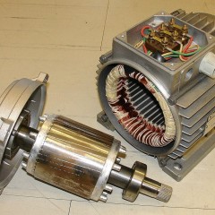
The supply wires are connected to the terminal block, which is located in a special box. It is called brno or borno. It leads wires from the windings and are fixed to the terminal blocks. The box itself is removed from the motor housing, as are the terminal blocks located in it.
Depending on the design of the engine, the brno can have 3 wires, and maybe 6 wires. If there are 3 wires, then the windings are already connected according to the star or triangle scheme and, if necessary, they cannot be switched quickly, for this you need to open the case, look for a connection, disconnect it and make bends.
If there are 6 wires in Brno, which is more common, then depending on the characteristics of the motor and the voltage of the mains (see below), you can connect the windings as you see fit. Below you see the brno and terminal blocks that are installed in it. For the 3-wire version, there will be 3 pins in the terminal block, and for the 6-wire version - 6 pins.

The beginning and ends of the windings are connected to the studs not just “anyhow” or “how convenient”, but in a strictly defined order, so that you can connect a triangle and a star with one set of jumpers. That is, the beginning of the first winding over the end of the third, the beginning of the second end of the first and the beginning of the third over the end of the second.

Thus, if you install jumpers on the lower terminals of the terminal block in a line, you get a winding connection with a star, and by setting three jumpers vertically parallel to each other - a triangle connection. On the “factory equipped” engines, copper busbars are used as jumpers, which is convenient to use for connecting - no need to bend the wires.

By the way, on the covers of the electric motor brunches, the location of the jumpers is often applied to these circuits.

Connection to a three-phase network
Now that we have figured out how the windings are connected, let's figure out how they connect to the network.
6-wire motors allow switching windings for different supply voltages. So electric motors with supply voltages became widespread:
- 380/220;
- 660/380;
- 220/127.
Moreover, more voltage for the star connection circuit, and less for the triangle.
The fact is that not always a three-phase network has the usual voltage of 380V. For example, on ships there is a network with an isolated neutral (without zero) of 220V, and in the old Soviet buildings of the first half of the last century, and now there is sometimes a network of 127 / 220V. While a network with a linear voltage of 660V is rare, more often in production.
You can read about the differences in phase and line voltage in the corresponding article on our website: https://my.electricianexp.com/en/linejnoe-i-faznoe-napryazhenie.html.
So, if you need to connect a three-phase electric motor to a 380 / 220V network, inspect its nameplate and find the supply voltage.

The electric motors on the nameplate of which is indicated 380/220 can only be connected with a star to our networks. If instead of 380/220 it is written 660/380 - connect the windings with a triangle. If you are not lucky and you have an old 220/127 engine, either a step-down transformer or a single-phase one is needed here a frequency converter with three-phase output (3x220). Otherwise, connecting it to the three phases of 380/220 will fail.
The worst case scenario is when the rated voltage of a three-wire motor with an unknown winding circuit. In this case, you need to open the case and look for the point of their connection and, if possible, and they are connected according to the triangle scheme - to remodel into the star scheme.
We figured out the connection of the windings, now let's talk about what are the schemes for connecting a three-phase electric motor to the 380V network. The circuits are shown for contactors with coils with a rated voltage of 380V, if you have 220V coils - connect them between phase and zero, that is, the second wire to zero, and not to phase "B".
Electric motors are almost always connected via magnetic switch (or contactor) You see the connection diagram without reverse and self-pickup below. It works in such a way that the engine will rotate only when the button on the control panel is pressed. In this case, the button is selected without fixing, i.e. closes or opens the contacts while being held pressed, like those used in keyboards, mice and doorbells.

The principle of operation of this circuit: when the “START” button is pressed, current begins to flow through the coil of the KM-1 contactor, as a result, the contactor’s armature is attracted and the power contacts of the KM-1 are closed, the engine starts to work. When you release the START button, the engine will stop. QF-1 is circuit breakerwhich de-energizes both the power circuit and the control circuit.
If you need you to press the button and the shaft starts to rotate - instead of the button, put the toggle switch or button with a latch, that is, the contacts of which after pressing remain closed or open until the next press.
But they do it infrequently. More often, electric motors are started from remotes with buttons without fixing. Therefore, another element is added to the previous circuit - the contact block of the starter (or contactor) connected in parallel with the “START” button. Such a scheme can be used to connect electric fans, hoods, machine tools and any other equipment whose mechanisms rotate in only one direction.

The principle of operation of the circuit:
When the QF-1 circuit breaker is turned on, voltage appears on the power contacts of the contactor and the control circuit. The STOP button is normally closed, i.e. her contacts open when they click on her.Through the “STOP” voltage is applied to the normally open “START” button, the block contact, and ultimately the coil, so when you press it, the coil control circuit will be de-energized and the contactor will turn off.
In practice, in a button post, each button has a normally open and normally closed pair of contacts whose terminals are located on different sides of the button (see photo below).
 When you press the “START” button, current begins to flow through the coil of the contactor or starter KM-1 (on modern contactors it is designated as A1 and A2), as a result, its armature is attracted and the power contacts of KM-1 are closed. KM-1.1 is a normally open (NO) block contact of the contactor, when voltage is applied to the coil, it closes simultaneously with the power contacts and shunts the “START” button.
After you release the “START” button, the motor will continue to work, since the current to the contactor coil is now supplied through the KM-1.1 block contact.
This is called "self-locking."
The main difficulty that newcomers have in understanding this basic scheme is that it does not immediately become clear that the button post is located in one place, and the contactors in another. At the same time, KM-1.1, which is connected in parallel with the “START” button, can actually be located within a dozen meters.
If you need the motor shaft to rotate in both directions, for example, on a winch or other load-lifting mechanism, as well as on different machines (turning, etc.) - use the three-phase motor connection scheme with reverse.

By the way, this circuit is often called the "reverse starter circuit."
Reversible wiring diagrams are two non-reversing wiring diagrams with some modifications. KM-1.2 and KM-2.2 are normally closed (NC) block contacts of contactors. They are included in the control circuit of the coil of the opposite contactor, this is the so-called "protection against fool", it is needed so that it does not happen interphase short circuit in the power circuit.
Between the button “FORWARD” or “BACK” (their purpose is the same as in the previous scheme for “START”) and the coil of the first contactor (KM-1), a normally-closed (NC) block contact of the second contactor (KM-2) is connected . Thus, when the KM-2 turns on, the normally-closed contact opens accordingly and the KM-1 will not turn on even if you press “FORWARD”.
Conversely, the NC from the KM-2 is installed in the control circuit of the KM-1, to prevent their simultaneous inclusion.
To start the engine in the opposite direction, that is, to turn on the second contactor, you must disable the existing contactor. To do this, press the STOP button, and the control circuit of the two contactors is de-energized, and after that, press the start button in the opposite direction of rotation.
This is to prevent a short circuit in the power circuit. Pay attention to the left part of the circuit, the differences in connecting the power contacts KM-1 and KM-2 are in the order of connecting the phases. As you know, to change the direction of rotation of an asynchronous motor (reverse), you need to swap 2 out of 3 phases (any), here the phases 1 and 3 are interchanged.
Otherwise, the operation of the circuit is similar to the previous one.
By the way, on the Soviet starters and contactors there were combined block contacts, i.e. one of them was closed, and the second open, in most modern contactors it is necessary to install a block contact prefix on top, in which there are 2-4 pairs of additional contacts just for these purposes.

Connection to a single-phase network
To connect a three-phase 380V electric motor to a single-phase 220V network, the most often used circuit is phase-shifting capacitors (starting and working). Without capacitors, the engine can start, but only without load, and you will have to spin its shaft by hand when starting.
The problem is that for the operation of blood pressure you need a rotating magnetic field, which cannot be obtained from a single-phase network without additional elements. But by connecting one of the windings through throttle, you can shift the voltage phase to -90˚ and using capacitor + 90˚ relative to the phase in the network. The phase shift issue was considered in more detail in the article: https://my.electricianexp.com/en/chto-takoe-aktivnaya-reaktivnaya-i-polnaya-moshhnost.html.
Most often, it is capacitors that are used for phase shift, not chokes. In this way, it is not rotating, but elliptical. As a result, you lose about half the power of the nominal. Single-phase AMs work better with this inclusion, due to the fact that their windings were originally designed and located on the stator for such a connection.

Typical motor connection diagrams without reverse for star or delta circuits are shown below.

Resistor the diagram below is needed for discharging capacitors, because after turning off the power, voltage will remain at its terminals and you can be shocked.
You can select the capacitor capacity for connecting a three-phase motor to a single-phase network based on the table below. If you observe a complex and protracted launch, you often need to increase the starting (and sometimes working) capacity.

Or count by the formulas:

If the engine is powerful or starts under load (for example, in a compressor), you need to connect a starting capacitor.

To simplify the inclusion of instead of the button "ACCELERATION" use "PNVS". This is a button for starting engines with a starting capacitor. She has three contacts, the phase and zero are connected to two of them, and through the third - the starting capacitor. On the front panel there are two keys - “START” and “STOP” (as on AP-50 machines).
When you turn on the engine and press the first key all the way, three contacts close, after the engine has unwound, and you release “START”, the middle contact opens, and the two extreme contacts remain closed, the starting capacitor is removed from the circuit. When you press the STOP button, all contacts open. The connection scheme is almost the same.

In detail about what is and how to properly connect the PNVS, you can see in the following video:
The connection diagram of the 380V electric motor to a single-phase 220V network with reverse is shown below. The switch SA1 is responsible for the reverse.
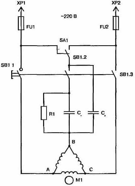
The windings of the 380/220 motor are connected by a triangle, and in 220/127 motors by a star, so that the supply voltage (220 volts) corresponds to the rated voltage of the windings. If there are only three outputs, and not six, then you will not be able to change the connection diagrams of the windings without opening. There are two options here:
- Rated voltage 3x220V - you're in luck, and use the above diagrams.
- Rated voltage 3x380V - you are less fortunate, since the engine may start poorly or not start at all if you connect it to a 220V network, but it’s worth a try, it will probably work!
But when connecting a 380V electric motor to 1 phase 220V through capacitors, there is one big problem - power loss. They can reach 40-50%.
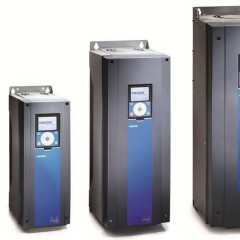
The main and effective way to connect without loss of power is to use a chastotnik. Single-phase frequency converters output 3 phases with a linear voltage of 220V without zero. Thus, you can connect motors up to 5 kW, for more power, converters capable of working with single-phase input are just very rare. In this case, you will not only get the full power of the engine, but also be able to fully regulate its speed and reverse it.
Now you know how to connect a three-phase motor for 220 and 380 Volts, and also what is needed for this. We hope the information provided has helped you sort out the issue!
Related materials: