What is a frequency converter, how does it work and what is it for
Definition
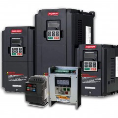
By definition, a frequency converter is an electronic power converter for changing the frequency of an alternating current. But depending on the performance, both the voltage level and the number of phases change. It may not be entirely clear to you why such a device is needed, but we will try to tell you about it in simple words.

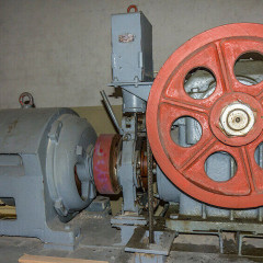
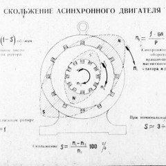
The shaft rotation frequency of synchronous and asynchronous motors (HELL) depends on the rotation frequency of the stator magnetic flux and is determined by the formula:
n = (60 * F / p) * (1-S),
where n is the number of revolutions of the HELL shaft, p is the number of pole pairs, s is slip, f is the frequency of the alternating current.
In simple terms, the rotor speed depends on the frequency and the number of pole pairs. The number of pole pairs is determined by the design of the stator coils, and the frequency of the current in the network is constant. Therefore, in order to regulate the speed, we can only control the frequency with the help of converters.
Device
In view of the foregoing, we re-formulate the answer to the question of what it is:
A frequency converter is an electronic device for changing the frequency of an alternating current, and therefore, the rotational speed of the rotor of an asynchronous (and synchronous) electric machine.
Graphic symbol in accordance with GOST 2.737-68 you can see below:

It is called electronic because it is based on a semiconductor switch circuit. Depending on the functional features and type of control, both the circuit diagram and the operation algorithm will be modified.
In the diagram below you see how the frequency converter is arranged:

The principle of operation of the frequency converter is as follows:
- Mains voltage is supplied to rectifier 1 and becomes a rectified pulsating one.
- In block 2, the pulsations are smoothed out and the reactive component is partially compensated.
- Block 3 is a group of power switches controlled by a control system (4) using pulse width modulation (PWM). This design allows you to get a two-level PWM-regulated voltage at the output, which, after smoothing, approaches a sinusoidal form. In expensive models, a three-level scheme has been used, where more keys are used. It allows you to achieve closer to the sinusoidal waveform. As semiconductor switches can be used thyristors, field effect or IGBT transistors. Recently, the last two types are most in demand and popular because of efficiency, small losses and ease of management.
- Using PWM, the required voltage level is formed, in simple words - this is how the sine wave is modulated, alternately including key pairs, forming line voltage.
So we briefly described how the frequency converter for an electric motor works and what it consists of. It is used as a secondary power source and not only controls the shape of the current supply network, but converts its value and frequency in accordance with the specified parameters.
Types of chastotniks and scope
Management methods
Speed adjustment can be carried out in different ways, both by the method of setting the required frequency, and by the method of regulation. Chastotniki according to the control method are divided into two types:
- With scalar control.
- With vector control.
The devices of the first type regulate the frequency according to a given U / F function, that is, the voltage changes along with the frequency. An example of such a dependence of voltage on frequency can be observed below.
It can be different and programmed for a specific load, for example, on fans it is not linear, but resembles a parabola branch. This principle of operation keeps the magnetic flux in the gap between the rotor and stator almost constant.

A feature of scalar control is its prevalence and relative ease of implementation. It is used most often for pumps, fans and compressors. Such chastotniks are often used if it is necessary to maintain a stable pressure (or other parameter), it can be submersible pumps for wells, if we consider domestic use.

In production, the scope is wide, for example, pressure control in the same pipelines and the performance of automatic ventilation systems. The control range is usually 1:10, in simple terms, the maximum speed from the minimum can differ by 10 times. Due to the peculiarities of the implementation of algorithms and circuitry, such devices are usually cheaper, which is the main advantage.

Disadvantages:
- Not too precise rev support.
- Slower response to regime change.
- Most often there is no way to control the moment on the shaft.
- With an increase in speed above the nominal, the moment on the motor shaft drops (that is, when we raise the frequency above the nominal 50 Hz).
The latter is due to the fact that the voltage at the output depends on the frequency, at the rated frequency the voltage is equal to the mains voltage, and the chastotnik does not know how to raise it higher, on the graph you could see an even part of the plot after 50 Hz. It should be noted that the dependence of the moment on frequency, it falls according to the law 1 / f, is shown in red in the graph below, and the dependence of power on frequency is blue.

Vector-controlled frequency converters have a different operating principle, here it’s not just the voltage that corresponds to the U / f curve. The characteristics of the output voltage vary in accordance with the signals from the sensors, so that a certain moment is maintained on the shaft. But why do we need such a control method? More precise and faster adjustment are the hallmarks of a vector-controlled frequency converter. This is important in such mechanisms where the principle of action is associated with a sharp change in load and torque on the executive body.

Such a load is typical for turning and other types of machines, including CNC. The accuracy of regulation is up to 1.5%, the adjustment range is 1: 100, for greater accuracy with speed sensors, etc. - 0.2% and 1: 10000, respectively.
There is an opinion on the forums that today the price difference between vector and scalar chastotniks is less than it was before (15-35% depending on the manufacturer), and the main difference is more firmware than circuitry. Also note that most vector models also support scalar control.
Benefits:
- greater stability and accuracy;
- faster response to load changes and high torque at low speed;
- wider range of regulation.
The main drawback is that it costs more than scalar ones.
In both cases, the frequency can be set manually or by sensors, for example, a pressure sensor or a flow meter (if we are talking about pumps), a potentiometer or an encoder.
All or almost all frequency converters have a soft start function, which makes it easier to start engines from emergency generators with virtually no risk of overloading it.
Number of phases
In addition to the response methods, the chastotniks differ in the number of phases at the input and output. So distinguish frequency converters with single-phase and three-phase input.
At the same time, most three-phase models can be powered by one phase, but with this application, their power decreases to 30-50%. This is due to the permissible current load on diodes and other power circuit elements. Single-phase models are available in the power range up to 3 kW.
Important! Note that with a single-phase connection with a voltage of 220V input, there will be an output of 3 phases of 220V, and not of 380V. That is, the linear output will be exactly 220V, in short. In this connection, common motors with windings designed for voltage of 380 / 220V need to be connected in a triangle, and those on 127 / 220V - in a star.
On the network you can find many offers such as “220 to 380 frequency converter” - this is in most cases marketing, sellers call any three phases “380V”.
To get real 380V from one phase, you must either use a 220/380 single-phase transformer (if the input of the frequency converter is designed for such a voltage), or use a specialized frequency converter with a single-phase input and a 380V three-phase output.

A separate and rarer type of frequency converters are single-phase inverters with a single-phase output 220. They are designed to regulate single-phase motors with capacitor starting. An example of such devices are:
- ERMAN ER-G-220-01
- INNOVERT IDD
Wiring diagram
In reality, in order to get a 3-phase output from a 380V frequency converter, you need to connect a 380V 3-phase input:

Connecting a chastotnik to one phase is similar, except for connecting the supply wires:

A single-phase frequency converter for a motor with a capacitor (pump or low-power fan) is connected as follows:

As you can see in the diagrams, in addition to the supply wires and wires to the engine, the frequency converter has other terminals, sensors, buttons of the remote control panel, buses for connecting to a computer (usually the RS-485 standard), and so on are connected to them. This makes it possible to control the motor through thin signal wires, which allows you to remove the frequency converter into an electrical panel.

Chastotniki are universal devices, the purpose of which is not only speed adjustment, but also protection of the electric motor from incorrect operating modes and power supply, as well as overload. In addition to the main function, the devices realize a smooth start-up of the drives, which reduces equipment wear and power loads. The principle of operation and the depth of parameter settings of most frequency converters allows you to save electricity when controlling pumps (previously control was carried out not due to pump performance, but using valves) and other equipment.
This is where we end the consideration of the issue. We hope that after reading the article you will understand what a frequency converter is and why it is needed. Finally, we recommend watching a useful video on the topic:
Surely you do not know: