How to install and connect a power limiter
Installation requirements
Both the consumer and the company supplying electricity are interested in installing a power limiter. The value of the electricity supplied must be within the specified limits (voltage, frequency, power).

The installation and connection of this device must be carried out by a trained specialist electrician. In case of self-installation, it is necessary to consider the following factors:
- Single-phase or three-phase voltage.
- Contractual load power (kW).
- Response time, when exceeding the specified parameters.
- Return time.
The type of device to be purchased depends on the first parameter. The second parameter also needs to be known to determine the type of purchased power limiter. Additionally may be required contactor. The third - will make it possible to adjust the power parameters of the connected load when the specified limit is accidentally exceeded - this parameter can be configured. The fourth will remind the consumer of the violation and will allow you to adjust the total consumption of the connected consumption devices and, if necessary, turn them off.
For the installation and installation of all types of limiters, the general requirements must be observed:
- Use the wire of the desired cross section, which is calculated by the consumed load.
- Contactors must be rated for current consumption.
- Limit access to live parts due to the high probability of electric shock.
- The settings of the limiter should be carried out taking into account the planned consumption, and not at the maximum values.
- In case of repeated operation of the protection, check the technical condition of electrical appliances for poor insulation, short circuit.
- In the event of a device malfunction, call a specialist.
Connection Features
OM-110
To install the OM-110 power limiter, the following features can be noted:
- Install OM-110 in a regular place (you can under Din rail).
- Connect the 220 V network, observing the correspondence of the zero and phase bus.
- Pass the load wire through a special hole - there is a current transformer, which is a sensor of consumed electricity.
- Connect the contactor according to the diagram. OM-110 only works if there is a contactor that will switch the voltage to the load.
- Set potentiometer shutdown power.
- Set the operating time of OM-110 in overload mode.
- Set the time the limiter returns to its original position after operation.
Connection diagram OM-110:

You can see the installation process in more detail in the video below:
After connecting, it is necessary to check the correct operation of the limiter. Apply power and connect less rated load. The green LED should be on. Then you need to connect a load that is higher than the installed one. The “overload” LED should light up, and after the time set by the “shutdown delay” controller, it should turn off all consumers. If necessary, the time can be adjusted. After disconnection, the reset is automatic. The return time can also be changed with the “re-enable” knob. Installation and configuration of the controller is over.
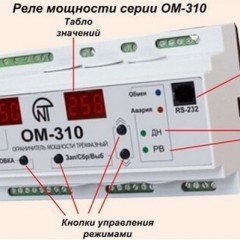
OM-310
OM-310 is used at a network voltage of 380 V and a power of 3-40 kW. The installation of a power limiter in this series does not differ from the previous one. The main difference is that you need to connect three phases of 380 V and a neutral wire to it. The front panel has two indicators that allow you to configure and control the operation of the device, as well as LED indicators. The configuration of this device is slightly different from the OM-110. The advantage is the ability to connect to a computer and configure it.
Installation consists of connecting all three phases and a neutral wire to the input terminals, as shown in the diagram below:

Visual installation instructions are provided in the video:
The load is connected via current transformers. Set the parameters of power consumption, shutdown time during overload and recovery time after shutdown. It is mandatory to use a contactor that commutes the load.
OM-630
OM-630 is a three-phase power limiter. Connection occurs according to the scheme. Only works with current transformers and load relays.
- Connect the phase wires and the neutral wire.
- Connect a contactor or several as required
- Pull load wires through the installed holes in the instrument housing
- Connect the power, after which the LED should light up, and after the set time the indicator is yellow and the load turns on.
The correct connection in the photo and diagram below is clearly provided:


The maximum power, shutdown time and recovery time are set using the switches. All controls are located on the front panel. In addition to the above functions, OM-630 has a trip counter function. When the limiter is activated for an hour more than a certain number of times, the load is disconnected for 10 minutes. This adjustment is also present on the front panel.
The video below clearly shows how to connect and configure OM-630:
These devices, regardless of brand and type, protect not only the electricity supplier from overspending and theft, but also the consumer from overloading the home electrical network and reducing the likelihood of a fire from overheating of worn electrical wiring, in the event of a mismatch between the network power and consumption. We hope you have found our tips and instructions provided for connecting the 110, 310 and 630 series power limiters.
It will be interesting to read: