Why do you need a spark protection device (USIs)
Design Features
The device is made for installation on a standard 35 mm DIN rail. The spark protection device has a non-separable IP40 housing with four contacts, IN and OUT, for connecting to the mains. On the right side of the case is a wiring diagram for the mains, with the symbols for the input and output, as well as the estimated load.


On the front side there is a free release lever for switching on and off the protected circuit. The regulator for setting the maximum permissible mains voltage, from 260 to 290 Volts, is also located there. To interact with the user, an LED is displayed, by the display modes of which it is possible to determine the status of the device and the controlled network.
Terminal IN (input) is located at the bottom of the device, and OUT (output to consumers) is located at the top. This solution is designed for ease of installation in a switchboard and save space in it. It is also worth paying attention to the fact that the conductor L is switched in the device, and N connects the input and output without interruption.
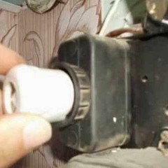
Included with the device is a means of monitoring the functioning of the protection zone, which simulates sparking in the network. It is made in the form of a plug for a standard outlet. With the help of this device, it is possible to determine the health of the ultrasonic scanning device, as well as to monitor the zone of functioning of the device protection (the sensitivity of the device). Using the monitoring tool, it is possible to determine the ability of the protection against sparking to sense the onset of hazardous processes at a certain distance, since the signal attenuates over long lines and is not detected by the protection device.
In the video below, you can familiarize yourself with the tests of the spark protection device, including ours:
Important! The area of operation may be affected by interference from switching power supplies of electrical appliances. In this case, the manufacturer recommends connecting problem consumers through a standard 3-meter extension cord.
In addition, a sticker is included with the decoding of the signals of the ultrasound detector, which is glued to the door of the ShchR.
Main technical characteristics of the spark protection device:

To learn more about the device in question, we recommend watching the video:
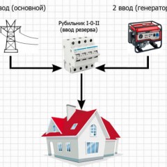
Wiring diagram
Possible connection options for UZIS-C1-40 are provided below:

After installation and connection no additional installations are required. When applying voltage to the network, the controller checks the value of the network voltage and the setting specified by the user. If everything is OK with the voltage, the green indicator light turns on.
Instrument light indication table:

To summarize
Installing an ultrasonic arrester in the protection and power supply control system reduces the possibility of fire of the wiring from unreliable contact and subsequent overheating of the problem area. The spark protection device completely cuts off the possibility of using unskilled “shabashnikov and hack workers” who do not comply or are not familiar with the rules of the EMP, and also save on customers. Therefore the collective Elecroexpert recommends the installation of UZIS-C1-40. In addition, when exceeding a dangerous voltage threshold in the network, this unit turns off, performing the function of the maximum voltage relay.
It is important to note that device maintenance does not require much time and specific knowledge. For the spark protection device to work correctly, it is enough:
- Make a visual inspection, remove dust from the surface.
- Tighten the screws on the device in compliance with electrical safety rules.
- Check the performance of an ultrasound scan with the use of a monitoring tool at least once every six months.
Finally, we recommend watching a video on which spark protection devices of various manufacturers are visually compared:
As you can see, there are quite a lot of low-quality products on the market that cannot fully fulfill their main purpose - to protect wiring from fire in the event of a spark. Therefore, it is important to give preference only to proven devices that have passed all the tests and proved that they can cope with the main task.