Transistor Health Check Technology
Tool preparation
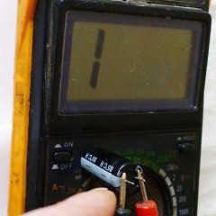
Every modern ham radio has a universal instrument called a digital multimeter. It allows you to measure direct and alternating currents and voltage, the resistance of the elements. It also allows you to check the performance of circuit elements. As a rule, a diode and a speaker are drawn next to the switch to the “dialing” mode (see photo in Fig. 1).

Figure 1 - The front panel of the multimeter
Before checking the element, you need to make sure the multimeter itself is working:
- The battery must be charged.
- When switching to semiconductor test mode, the display should show the number 1.
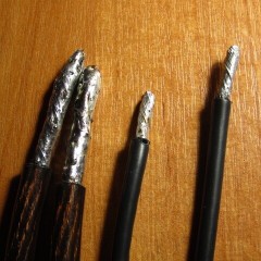
- The probes must be in good condition, since most of the devices are Chinese, and a wire break in them is a very common occurrence. You need to check them by leaning the tips of the probes against each other: in this case zeros will appear on the display and a beep will sound - the instrument and probes are working.
- The probes are connected according to the color coding: the red probe is in the red connector, the black in the black connector with the inscription COM.
If you do not know how to use this device, we recommend that you read the detailed instructions for dummies about how to use a multimeter!
Verification Technologies
Bipolar
The structure of a bipolar transistor (BT) includes 2 p-n or 2 n-p junctions. The findings of these transitions are called emitter and collector. The output of the middle layer is called the base. Simplified BT can be represented as two on-board diodes, as shown in Figure 2.

Figure 2 - NPN model and its diode “analog”
It is not difficult to check the bipolar transistor with a multimeter, which is what you are now convinced of. As is known, the main property of the pn junction is its one-sided conductivity. When a positive (red) probe is connected to the anode, and black to the cathode, the forward voltage at the junction in millivolts will be displayed on the multimeter display. The magnitude of the voltage depends on the type of semiconductor: for germanium diodes this voltage will be of the order of 200-300 mV, and for silicon from 600 to 800 mV.In the opposite direction, the diode does not pass current, so if you swap the probes in places, then the display will show 1, indicating an infinitely large resistance.
If the diode is “broken”, then most likely a sound signal will be heard, and in both directions. If the diode is “open”, then the unit will be displayed on the indicator.
Thus, the essence of the transistor health check is the “ringing” of p-n junctions base-collector, base-emitter and emitter-collector in direct and reverse connection:
- Base-collector: The red probe connects to the base, black to the collector. The connection should work as a diode and conduct current in only one direction.
- Base-emitter: The red probe remains connected to the base, the black is connected to the emitter. Similarly to the previous paragraph, the connection must conduct current only when directly connected.
- Emitter-collector: At a faulty transition, the resistance of a given section tends to infinity, as the unit on the indicator will talk about.
When checking the operability of a pnp of the “diode” type, the analog will also look like it, but the diodes will be connected the other way around. In this case, the black probe is connected to the base. The emitter-collector junction is checked in the same way.
In the video below, a check of a bipolar transistor with a multimeter is clearly shown:
Field
Field effect transistors (PTs) or "field devices" are used in power supplies, monitors, audio and video equipment. Therefore, the need for verification is more often encountered by hardware repair technicians. You can also independently check such an element at home using a conventional multimeter.
Figure 3 shows the structural diagram of the PT. The outputs Gate (gate), Drain (drain), Source (source) can be located in different ways. Very often, manufacturers label them with letters. If there is no marking, then it is necessary to consult the reference data, having previously known the name of the model.

Figure 3 - Block diagram of the PT
It should be borne in mind that when repairing equipment in which the PTs are installed, the task often arises of verifying operability and integrity without desoldering an element from the board. Most often, powerful field-effect transistors installed in switching power supplies fail. It should also be remembered that "field workers" are extremely sensitive to static discharges. Therefore, before checking the field effect transistor without evaporating, it is necessary to put on an antistatic bracelet and observe safety precautions.

Figure 4 - Antistatic wristband
You can check the PT with a multimeter by analogy with the continuity of the transitions of a bipolar transistor. A working “polevik” has infinitely high resistance between the terminals, regardless of the applied test voltage. However, there are some exceptions: if you put a positive tester probe on the gate, and a negative probe on the source, the gate capacitance is charged, and the transition opens. When measuring the resistance between the drain and the source, the multimeter may show some resistance value. Inexperienced craftsmen often accept this phenomenon as a sign of malfunction. However, this does not always correspond to reality. Before checking the drain-source channel, it is necessary to short-circuit all the PT terminals to shorten the capacitances of the junctions. After that, their resistance will again become large, and you can re-check whether the transistor is working or not. If such a procedure does not help, then the element is considered inoperative.
"Field workers" standing in high-power switching power supplies often have an internal diode at the drain-source transition. Therefore, this channel behaves like a regular semiconductor diode during verification. In order to avoid a false error, before checking the transistor with a multimeter, make sure that there is an internal diode. Swap the tester probes. In this case, one should be displayed on the screen, which indicates infinite resistance.If this does not happen, then, most likely, the PT is “broken.”
The technology for checking the field effect transistor is shown in the video:
Composite
A typical composite transistor or Darlington circuit is shown in Figure 5. These 2 elements are located in the same housing. There is also a load resistor inside. Such a model has similar conclusions as the bipolar one. It is easy to guess that you can check the composite transistor with a multimeter in the same way as the BT. It should be noted that some types of digital multimeters in test mode have a voltage of less than 1.2 V on the terminals, which is not enough to open the pn junction, in which case the device shows an open circuit.

Figure 5 - Darlington diagram
If after reading the article you still do not fully understand how to check the transistor with a multimeter, the video tutorial below will allow you to clearly see the verification technology:
Thus, the task of checking this element of the circuit is reduced to successive “ringing” of p-n junctions, and if they are working, the device can be considered working. We hope that now you know how to check the transistor with a multimeter at home!
We advise you to read:


“However, there are some exceptions: if you put the positive probe of the tester to the gate, and the negative to the source, the gate capacity will be charged, and the transition will open. When measuring the resistance between the drain and the source, the multimeter may show some resistance value. "
The question is: when measuring the resistance between the drain and the source, can the multimeter show some resistance value in both positions of the probes?
To test bipolar by the good / bad principle, it is better to make a simple multivibrator. There is sound - good, no sound - not good. Convenient and easy.
A good option, but for convenient mounting-dismantling, you can use a "mother" type block in a multivibrator (they are also called dupont). But now it’s easier to check with the help of “transistor testers” https://my.electricianexp.com/en/tranzistor-tester.html