Rules for determining phase, zero and grounding in the network
Using an indicator screwdriver
The sequence of actions depends on which wiring system is installed in the room. Consider the rules for determining the phase and neutral wires in different cases.
Two wire network
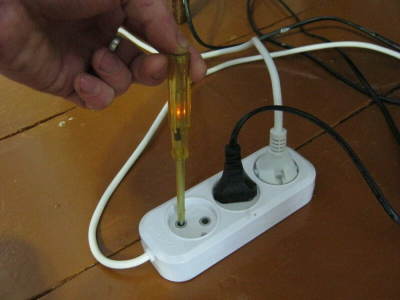
This wiring option is found in old houses. According to modern terminology, this system is designated TN-C. Its essence lies in the fact that the zero working wire, grounded at the power substation, combines the role of a protective ground (PEN). In the IT system, there is also only a phase and working neutral conductor, but it is not used in ordinary residential and industrial premises. In a two-wire network, a separate ground wire is simply absent, that is, there is only a phase and zero. It is very simple to determine them: we touch the indicator sequentially to each of the current-carrying conductors, the phase ignites the indicator lamp, as shown in the photo below:
The system is outdated. There are three terminals on the plug of any modern electrical appliance. Wiring must be three-wire, with the exception of the lighting group.
Three wire network
In this embodiment, three wires enter the house or apartment. Such networks have several varieties. In system TN-S the working zero and protective earth go separately from the power substation, where both are connected to the working ground. With this type of wiring, determining the purpose of the wires can be done as follows:
- in the shield or in the junction box, use the indicator to determine the wire on which the phase is present;
- the two remaining ones are the working and protective zero (earth), disconnect one wire from them on the shield;
- if you disconnect the working zero, all the electrical equipment in the apartment will stop working, which means that the remaining conductor is earth, or protective earth.
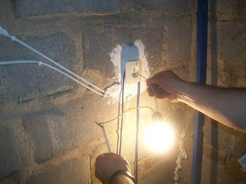
Now it remains to determine in the outlet among the three wires on which of them phase, zero and ground. If it is not possible to find the insulation color, the determination of their functions can be performed by improvised means, without devices. To do this, you need to take a cartridge with a screwed-in lamp and wires brought out. The definition is carried out as follows. We touch the phase wire with one conductor from the cartridge (the phase has already been found using the indicator), and the second one touches the two remaining ones. If the operating zero is switched off on the panel, the lamp will light up only when connected to protective ground, and vice versa.
The video below clearly shows how to determine the phase, zero and ground with an indicator screwdriver:
Another variation of the TN system is wiring TN-C-S. In this case, the neutral wire is split into a working zero and protective ground at the entrance to the house. Here, to determine the purpose of the conductors, you can apply the sequence of operations described for the TN-S system. An additional opportunity is added, having examined the place of separation of the PEN, to determine where the working and protective zero (ground) are along the cross-section of the core in the wire.
In case the grounding is made according to the system TT, the object (private house) has its own grounding device, from which the protective grounding is wired. Under these conditions, as a rule, it is possible to determine the phase, zero and earth by monitoring the grounding conductor along the route of its laying.
Definition with a multimeter or tester
To begin with, it is best to determine the phase using a screwdriver combined with an indicator. We will proceed from the fact that if there is a multimeter in the farm, an indicator will be found for sure. In extreme cases, you can do the following. In some cases, using a multimeter to determine the voltage between the wire and the heating or water pipe can help. Unfortunately, the result here is not always predictable. Most often, the voltage between the phase and the heating system is close to 220 V, in any case, it should be higher than between the same heating and zero. The picture may change, for example, if a thieving neighbor uses heating pipes as a working ground.
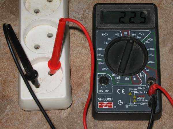
In three-wire circuits, the multimeter will show the operating voltage between the conductor to which the phase is applied and any of the other two. The determination of which zero is working, and which is ground, can be carried out according to the method described above, that is, by disconnecting one of the incoming zeros on the shield and using the control lamp.
What else is important to know?
Sometimes the determination of the purpose of current-carrying conductors can be facilitated by knowledge of their generally accepted color marking:
- Zero can be marked with the Latin letter N. The commonly accepted insulation color is blue or blue. Another option for coloring the insulation is a white stripe on a blue background.
- Land is marked in Latin PE. In a grounding system that combines the functions of protective and working zero, PEN is designated. The color of the insulation used is yellow, having one or two strips of a bright green hue.
- The phase can be indicated by the Latin letter L or marked as the phase of a three-phase electrical network, that is, A, B or C. The insulation color can be arbitrary, but not repeating those that indicate the earth (protective earth) or neutral conductor. In most cases, it is red, brown or black.
It is useful to know the rules for wiring. It can also help determine where phase, zero and ground are. The phase should always come to the switchboard on circuit breaker or fuse. The zero core can be mounted on a bus of a special design, which has several terminals. In metal panels and terminal boxes of the old type, zero or ground were mounted under the nut with a bolt welded to the box body. These rules can facilitate the determination of the functions of incoming conductors. Learn more about how to determine phase and zero without instruments, you can from our separate article.
Now you know how to determine the phase, zero and ground with a multimeter or with an indicator screwdriver. We hope that the recommendations provided have helped you resolve the issue yourself!
Surely you do not know:

