Overview of UZM-50Ts: what kind of apparatus and how to connect it
Device description
The name "UZM-50TS", stands for "Multifunction protection device." It is designed to protect the home electrical system from increased, undervoltagearising from phase imbalance and with poor electrical conditions. In addition, UMM will protect against discharges and sparking in electrical wiring, as well as not too powerful high-voltage pulses in the network (up to 1.2 kV), the so-called "interference voltage".
On the front panel of the UZM-50C you will see a minimum of controls, namely a couple of buttons and a seven-segment three-digit indicator (display, in simple terms). The real-time display shows voltage or current. Use the buttons to configure the device. Custom items are displayed accordingly.

The buttons have a dual purpose: the first is “select” or “+”, and the second is “On / Off”, it is also “-”.
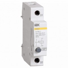
As you can see from the photo, the dimensions of the UZM-50Ts are equivalent to two modules in the electrical panel on din rail, dimensions in width 35 mm.
Let's look at the main technical characteristics of the UZM-50Ts:

Attention! Carefully tighten the screw terminals; their maximum torque is 3 Nm.
Analogs from this manufacturer
It is worth noting that the UZM-50Ts is not the first protective device in the manufacturer's line, it replaced the popular UZM-51M. The main difference from UZM-51M is that the 51M model was a voltage relay with varistor protection, it was most often installed in conjunction with a VAR-M01-083 voltammeter or the like.
UZM-50Ts combines the advantages of these two devices in one housing, and takes only 2 modules in the electrical panel. The above listed devices (51M and BAP) each occupied 2 modules - a total of 4.
In the figure below, you see a line of similar universal protective devices from the Meander computer:

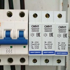
This is what three voltammeters and UZM-51M look like in the electrical panel:

And so UZM-50Ts, the difference in two modules is palpable even for the amateur:

Wiring diagram
Let's figure out how to connect the UZM-50TS. The scheme is simple: incoming phase and zero to the upper contacts. To the lower contacts are phase and zero, which go to the load. This is the preferred setup. When triggered, the phase opens, subject to proper installation.

But the instructions provide another scheme. The difference is, for example, in connecting zero.

Note: to install UZM-50C in a three-phase network, such a connection scheme is repeated three times for three devices for each phase, respectively. An example of the circuit you see below:

How it works and how to configure the relay
After applying voltage to the UZM-50C, there is a slight time delay, it is user-configurable from 2 seconds and above. After switching on the device contacts, power is supplied to the load, and its value is displayed.
You can set the upper and lower threshold of the permissible voltage, upon reaching which the load will be disconnected. The setting allows you to adapt the device to the characteristics of your power supply.
Due to the fact that there are only two buttons from the controls, many users experience difficulties in mastering the control and settings of the device. This process is described in detail in the instrument manual.
You can view or download the instructions for the UZM-50Ts by clicking on the link: instruction for ultrasound.
Consider the basic principles of working with the device menu. Briefly press the right button (on / off or "+"), the relay will turn off and the load will be de-energized, turn it back on in the same way.
Briefly press the left button (“select” or “-”), the mode switching will begin. Consider them in the order of pressing “-”, and in parentheses indicate the designation of the mode on the display:
- (A) Ammeter - current in the circuit now.
- (R) Wattmeter - power consumption.
- (Uhi) Upper cut-off threshold - just shows the set limit, and if in this mode you hold down the “-” button for 5 seconds, then you will enter the setting mode of the upper cut-off threshold setting. After that, use the “+” and “-” buttons to change the value. The default setting is 270 volts.
- (Ulo) Lower shutdown threshold - if you hold down the “-” button for 5 seconds, you will enter the setting mode for the lower shutdown threshold. After that, use the “+” and “-” buttons to lower or raise the value. The default is 170 volts.
- (Ton) Re-enable delay - also set by long pressing “-”, by default - 5 seconds.
- (U ^) - shows to what level the maximum voltage increased in the network, to reset, hold “-" for 5 seconds.
- (U \ /) - minimum voltage in the network, reset similar to the previous one.
- (off) - the number of shutdowns, reset is similar.
Attention! Do nothing to save the settings of the trip thresholds and the timer; after 5 seconds, this will happen automatically.
In the video below you can see the main features of the UZM-50TS:
Nevertheless, with the full range of functions, the UZM-50Ts is not a replacement for other protective devices, this is stated on the manufacturer’s website. Therefore, for greater reliability, it should be used in conjunction with full SPD and other devices. This is primarily due to the fact that varistor At the entrance of the ultrasound machine is not too powerful - it is able to absorb only up to 200 J of energy. Therefore, it cannot be considered as a full-fledged SPD, and the connection circuit of the SPD for these purposes involves the "ground". This device can be replaced by a bunch of voltage relays, for example RN-113 and SPD.
This is where we end with the considered characteristics and functions of the UZM-50Ts. We hope that now you understand why this unit is needed and how to install it in the shield.
Related materials: