How to connect zero and ground in the electrical panel and in what cases it is necessary
Types of protection against electric shock
In accordance with paragraph 1.1 GOST 12.1.030-81 protective grounding or grounding (zero-earth connection) is designed to protect people from electric shock in case of insulation damage when they touch metal non-conductive parts of electrical equipment.
Grounding - this is a deliberate or accidental electrical connection of metal parts of electrical equipment, electrical installations, or network points to a grounding device, bus, or other protective equipment (clause 01-10-09 GOST R 57190-2016).
It can be armature in the ground, building structures or special electrodes. This measure is a mandatory deliberate protection of both residential and non-residential property.
Zeroing - this is a deliberate connection of metal parts that are not energized in normal condition with a protective earth conductor (neutral earthed transformer or generator).
In accordance with clauses 1.1.2, 1.1.3, 1.7 of GOST 12.1.030-81, grounding must be carried out by electrical connection of the metal parts of the electrical equipment with the grounded point of the power supply using a neutral protective conductor (PE).
For zero protective and grounding conductors, you can use: special conductors, as well as metal structures of buildings and structures.
Protective grounding and grounding of electrical equipment must be carried out without fail when using alternating current voltage with a nominal value of 220 (1 phase) and 380V (3 phases) and higher and direct current voltage of 440V and higher. In addition, according to Section 1.7.13 PUE power supply of electrical receivers should be performed from a network 380/220 V with a grounding system TN-S or TN-C-S. 
Earthing systems
In accordance with paragraph 1.7.3 of PUE 7, when using electrical equipment designed for voltages up to 1 kV, grounding methods are used:
- TN - zero power source (from a substation or generator) is deafly connected to ground;
- TN-C - TN, where the protective (PE) and working (N) neutral wires are combined in one PEN conductor;
- TN-S - TN, where PE and N neutral wires are separated along the entire line from the substation;
- TN-C-S - TN, where PE and N are separated in a specific section of the circuit, and from the substation to this section they are combined;
- TT - zero from the substation is deafly grounded, and unprotected electrically conductive structures of electrical equipment are connected to a grounding device that is not connected to a grounded zero from the substation;
- IT - zero is isolated from the ground or connected to the ground through high resistance, and unprotected metal structures of electrical equipment are connected to the ground.
Explanation of symbols, the first of which indicates the zero position of the power supply unit in relation to the earth:
- T - grounded zero (neutral);
- I - isolated neutral.
The second symbol is the position of unprotected metal structures in their location to the ground:
- T - connection to the ground of open conductive parts and metal structures, regardless of whether the neutral is grounded from the substation;
- N - connection of the conductive parts to the grounded zero of the power supply unit.
The symbols following N determine the connection of the working and protective zero wires with the ground electrode at the consumer or the separation of zero at the substation:
- S - working (N) and protective (PE) zeros - these are different, separated conductors;
- C - connection in a single wire (PEN) of the role of zero working and protective conductors.

When grounding, the zero protective and phase wires are selected so that when an insulation breakdown occurs on the case or the neutral conductor, the arising short-circuit current ensures that the circuit breaker trips or the fuse blows.
Differences between grounding and grounding
Grounding and grounding methods have different protective effects. Zeroing provides instantaneous operation of circuit breakers when a phase is shorted to the housing. At the same time, there is a blackout of the connected consumers of electricity, for example, machines, transformers.
But this does not save a person from exposure leakage currentas well as neutral conductor break voltage will appear on the electrical enclosures. In this connection, neutralization in its pure form is not used.
At the same time, in electrical equipment with a four-wire network with a grounded neutral and a zero wire voltage of up to 1000 V, grounding is the main means of protection.
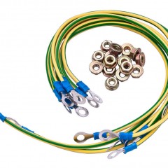
The implementation of grounding and grounding schemes has a number of differences. One of the main ones - for grounding it is necessary to use cables with a separate core. The cross section of PE conductors may be smaller than the phase cross section, and their insulation always has a yellow-green color.
One of the main advantages when implementing grounding is the use of a cheaper cable. The advantages of grounding - it always works, does not require frequent quality control of the connection, enough once a year.
The connection of zero with the "ground" (grounding) in a private house or apartment is not only not necessary, but can also be unsafe. If the neutral wire burns out or breaks in the floor board, then household devices operating from 220 V will receive a voltage of a much larger magnitude, which will lead to their failure, in addition, hazardous voltage will appear on their cases.
By "ground" here is meant a conductor connected to the housings of electrical appliances and the grounding contacts of outlets.
To ensure the greatest safety, a grounding and grounding device can be recommended at the same time. For this, the TN-C-S system is implemented - grounding and zero separation at the entrance to the house, in the introductory common house electrical switchboard of the ASU.
How to connect zero to ground
Incorrect connection of ground to ground can cause a tragedy, instead of protection. In a common house input device (ASU) must be produced separation of combined zero into working and protective conductors. Then the protective zero should be spread to the shields on the floors, and then to the apartments.
It turns out a five-wire network:
- 3 phases;
- N;
- PE.
PE must be connected to the third pin of the sockets. In old houses there is a four-wire network:
- 3 phases;
- combined zero
If the PE conductor is made in the form of an aluminum bus, then its cross section must be at least 16 mm²if the copper busbar (brass) is not less than 10 mm2. This rule is true for the ASU, the rest should be guided by the table below.
| Section of phase conductors, mm2 | The smallest section of protective conductors, mm2 |
| S≤ 16 | S |
16 | 16 |
|
| S> 35 | S / 2 |
Automata and other disconnecting devices cannot be installed on the PE protective conductor; it must be non-disconnectable. It is necessary to separate the combined zero of PEN to automatic machines and RCDs, after them they should not be connected anywhere!
Prohibited:
- connect the protective and zero contacts in the socket with a jumper, because when a zero break occurs, dangerous phase voltage will appear on the housings of household appliances;
- connect the neutral and protective conductors with one screw (bolt) on the bus in the shield;
- PE and N must be connected to different buses, while each wire from each apartment must be bolted with its own screw (bolt). It is necessary to provide measures against loosening the bolts and protecting them from corrosion and mechanical damage (Clause 1.7.139 of PUE 7).

Such a connection is used for modern power supply of residential premises or private houses. That complies with the requirements of PEU-7 (paragraph 7.1.13) for AC and DC networks with a voltage of 220/380 volts. After separation, combining them is strictly prohibited.
In a private house, we often get two or four wires from the power transmission line. Most often there are 2 situations:
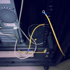
Situation No. 1 is a good case. Your electrical panel stands on a support, re-grounding is driven in under it. There are two PE and N buses in the electrical panel. Zero from the support and a wire from the ground electrode go to the PE bus. There is a jumper between the PE bus and N, a working zero goes to the house from the N bus, and a protective zero goes to the house from the PE bus. PE and N buses can be installed in the house in a switchboard, then zero to ground is connected on one bus in the metering panel as in the photo below.
 The point is to connect zero and ground at the input to all RCDs and diflavtomats and from this point to the consumers already conduct phase, neutral and ground.
Such shields are now often assembled when connecting new private homes to the mains. In this case, the introductory machine is installed in phase, zero from the high-voltage line goes directly to the counter, and zero separation (connection to the ground electrode) is made after it. Less often this is done even before the counter, but often energy sales are against such a decision. Why? Nobody knows, they argue the possibility of theft of electricity (the question is, how?).
 Situation No. 2 - The metering panel can be both on a support, and in the house or on its facade, it does not matter. You have a sealed opening machine and a counter, respectively, you have one or three phases and zero. How to make grounding and is it necessary to connect it to zero? If the VLEP is new, it is necessary. As in the previous case, you get the TN-C-S system. Then: they connect the zero from the meter to the PE bus, to it the wire from the ground electrode (which you will do yourself on your site).

If the high-voltage transmission line is old, it is not necessary to connect zero and earth (Chapter 1.7. PUE p. 1.7.59). Make a TT system (without connecting PE to N). In this case, be sure to use RCD!
In both situations, each wire on the tires must be tightened with its own bolt - do not put several PE or N-conductors under one bolt (or screw).
If you live in an apartment, we recommend reading this article: https://my.electricianexp.com/en/kak-sdelat-bezopasnoe-zazemlenie-v-kvartire.html.