How to make a photo relay at home - the easiest way
One of the main elements of automation in street lighting, along with timers and motion sensors, is a photo relay or twilight relay. The purpose of this device is to automatically connect the payload when it is dark, without human intervention. This device has also gained immense popularity due to its low cost, accessibility and ease of connection. In this article, we will analyze in detail the principle of the twilight switch and the nuances of its connection, as well as tell you how to make a photo relay with your own hands. This will not take much time and effort, but you will be pleased to use a self-assembled device.
Relay design
The main element of the relay is a photosensor, can be used in circuits photoresistors, diodes, transistors, photovoltaic cells. When the illumination on the photocell changes, its properties, such as resistance, states of the P-N junction in diodes and transistors, as well as the voltage at the contacts of the photosensitive element, respectively change. Further, the signal is amplified and the switching of the power element switching the load occurs. As output control elements using relays or triacs.
Almost all purchased items are assembled on a similar basis and have two inputs and two outputs. The input voltage is 220 volts, which, depending on the set parameters, also appears at the output. Sometimes a photo relay has only 3 wires. Then zero is common, a phase is applied to one wire, and with the necessary illumination it is connected to the remaining wire.


At connecting photo relay it is necessary to read the instructions, pay special attention to the maximum power of the connected load, the type of lighting lamps (incandescent, gas discharge, LED bulbs). It is important to know that lighting relays with a thyristor output will not be able to work with energy-saving lamps, as well as with some types dimmers due to design features. This nuance must be taken into account so as not to damage the equipment.
Let's look at several schemes for self-assembly of a twilight switch at home. For an example, let’s figure out how to make a triac nightlight with a photocell.
Assembly instruction
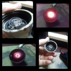
This is the most elementary photo relay circuit of several parts: the Quadrac Q60 triac, the R1 reference resistor, and the photo of the FSK element:

In the absence of light, the triac key opens fully and the lamp in the night light shines completely. With increasing illumination in the room, a voltage shift occurs at the control contact and the brightness of the lamp changes, up to the complete attenuation of the bulb.
Note that there is a life-threatening voltage in the circuit. Connect and test it with special care. And the finished device must be in a dielectric housing.
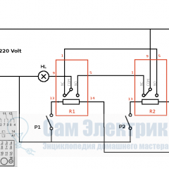
The following circuit with relay output:

Transistor VT1 amplifies the signal from the voltage divider, which consists of a photoresistor PR1 and a resistor R1. VT2 controls the electromagnetic relay K1, which can have both normally open and normally closed contacts, depending on the purpose. The diode VD1 shunts the voltage pulses during the trip of the coil, protecting the transistors from failure due to surges of the reverse voltage. Having considered this circuit, you can find that its part (highlighted in red) is close in functionality to the ready-made assemblies of the relay module for arduino.

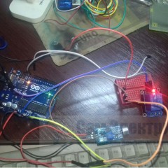
Having slightly altered the circuit and supplemented it with one transistor and a solar photocell from an old calculator, a prototype of the twilight switch was assembled - a home-made photo relay on a transistor. When lighting the solar cell PR1, the transistor VT1 opens and sends a signal to the output relay module, which switches its contacts, controlling the payload.

If you still have questions, then watch the video, which also details how to make a photo relay yourself:
Here, in fact, all the information about assembling the photorelay with your own hands. We hope that the provided diagrams and video tutorials have helped you make the twilight switch out of handy tools!
Surely you do not know:


So, what happens? .... In a relay-gated circuit, do you need to use relays with normally-closed contacts? ...
Based on VT1 saturation voltage. VT1 in operation, relay on, relay contacts open, load off. It's light. With insufficient lighting, the relay is de-energized, the relay contacts shorted the load. Conclusion: We take a relay that has normally closed NC and normally open NO contacts.
Can I have a photo of the circuit board for this circuit? And assembly drawing
Upon transition from the switching state, the relay will “click” for at least a minute until the photocell confidently opens the transistor. Need to add a capacity of at least 200 microfarads. to increase the transition time.
or better yet, a threshold element!
A good working circuit assembled 10 such pieces, there is no relay bounce, it is well regulated to the level of inclusion in the dark. I will put two relays one on the sensor board, and the second in the lamp, where the power supply for the circuit. The second relay “direct” Н О contacts turns on the lamp .In parallel to the coil of the second relay, I put a capacity of 2000 microfarads for the delay of shutdown in a thunderstorm, etc. Relays do not mind they have a penny for the Chinese. The power supply is impulse from any unnecessary equipment. Without a transformer refused, it does not work for a long time and the zener diode burns. And Chinese with Aliekspres and therefore burn more than a year do not work. By the way, it’s convenient to mount such a homemade product in burnt out.
A good working circuit assembled 10 such pieces, there is no relay bounce, it is well regulated to the level of inclusion in the dark. I will put two relays one on the sensor board, and the second in the lamp, where the power supply for the circuit. The second relay “direct” Н О contacts turns on the lamp .In parallel to the coil of the second relay, I put a capacity of 2000 microfarads for the delay of shutdown in a thunderstorm, etc. Relays do not mind they have a penny for the Chinese. The power supply is impulse from any unnecessary equipment. Without a transformer refused, it does not work for a long time and the zener diode burns. And the Chinese therefore, they have been working with Aliexpress for more than a year. By the way, it’s convenient to mount such a homemade product in burnt out.