How to work with current clamps?
Principle of operation
As the name suggests, TCs or Dietze pincers are designed to measure the strength of an alternating current in a circuit without breaking it. The operation of a current-measuring instrument is based on the principle of a simple current transformer. In this case, the primary winding is a bus or cable with a measured current, and the capture of ticks, inside which a second multi-turn winding is located, wound on a magnetic core made of ferromagnetic material, is a secondary one. The alternating current in the wire (primary coil) creates an alternating magnetic mole, the lines of force of which pass through the secondary winding, exciting an emf in it, in proportion to the magnitude of the current in the first coil. Thus, by measuring the emerging EMF, one can find the current strength in the first coil (wire).
Design
Modern clamp meters, regardless of the manufacturer or modification, contain the following elements: magnetic cores with a movable bracket-lever, a switch for measuring ranges, a screen, output connectors for probes (in this case, the clamp can be used as a normal multimeter) and a button for fixing current measurements (photo below )

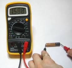
Figure 1 - TC S-line DT 266 FT
Most modern current meters also include an internal transformer with a diode bridge. In this case, the terminals of the secondary winding are connected via a shunt. Depending on the range of measured current forces, the current clamp can be one-handed (for voltages up to 1000 V) and two-handed with additional insulated handles (for voltages from 2 to 10 kV inclusive). Current measuring devices designed to measure more than 1 kV have an insulator length of less than 38 cm, and handles of at least 13 cm.
As a rule, the safety category and the maximum measured current are indicated on the instrument case. For instance:
- CAT III 600 V - this means that the device is protected against short-term surges in the equipment during operation in stationary networks with voltage up to 600 V.
- CATIV 300 V - this means that the device is protected from power surges inside the equipment of the primary level of power supply voltage up to 300 V. An example of such equipment is a conventional electric meter.
Work safety rules
Clamp meters may only be used indoors or outdoors in dry weather. Current strength can be measured both on cables coated with insulation and on bare cables. Before use, a person needs to wear protective gloves, and put a dielectric base under his feet and put on special shoes.
Measurement order
As a rule, the use of clamp meters does not cause special difficulties. Before using the tool, it is worth paying great attention to safety measures, as mentioned earlier.
How to use clamp meters:
- Set the desired range on the switch.
- Press the button for opening the magnetic circuit.
- Clasp a single conductor in the AC or DC network (if this feature is supported by the device).
- Position the current clamp perpendicular to the direction of the wire.
- Read the display.
Often the difficulty of using clamp meters lies in the isolation of a single conductor: when trying to take readings from a conventional cable coming from an outlet, zero should be displayed on the screen. This is because the currents of the phase conductor and the neutral conductor are equal in magnitude and opposite in direction. Consequently, the magnetic fluxes generated by them are mutually compensated. If the current readings are non-zero, then this indicates the presence of circuit leakagewhose value is equal to the value obtained. Therefore, for measurements, you need to find a place where the wires are separated and highlight a single core. As such a place, you can use a switchboard or a place to connect a phase wire to a circuit breaker. Nevertheless, this cannot always be done, which limits the scope of clamp meters.
If a unit is displayed on the screen during measurements, this indicates that the current in the wire is outside the measurement range. In this case, it is necessary to increase the range of current measurements with the switch. When taking measurements in hard-to-reach spots, you can use the Hold button. With its help, you can record the result of the last measurement and see it by removing the ticks. By pressing Hold a second time, you can reset the value.
You can clearly see how to work with clamp meters, you can on the video instructions below:
Useful "trick"
If it is required to measure a small value of current strength, then it is necessary to make several turns of wire on an open magnetic circuit, and set the range switch to a minimum. After this, it is necessary to take readings, and to determine the actual value, divide the resulting number by the number of wound turns.
Usage example
Here is an example of how to use clamp meters when measuring load in a 220 V network, for example in an apartment. In this case, the switch must be set to the AC 200 position. Next, with the current clamps, grasp the insulated conductor and take readings. After that, the obtained value of the current strength needs to be multiplied by the voltage in the network 220 V. For example, if the device shows 5 A, then the consumed power in the network will be P = U * I = 5 * 220 = 1100 W or 1.1 kW. The obtained value can be used to verify the operation of electricity meters.
Finally, we suggest watching a video that clearly shows how to use the current clamps DT-266 and Fluke 302+, which are quite popular today:
That’s the whole instruction on how to use clamp meters yourself.As you can see, there is nothing complicated. The main thing is to observe safety measures and carefully approach measurements. We hope that our tips and a visual video instruction clearly explained the procedure for you!
It will be interesting to read: