How to connect a well pump?
What do you need to prepare?
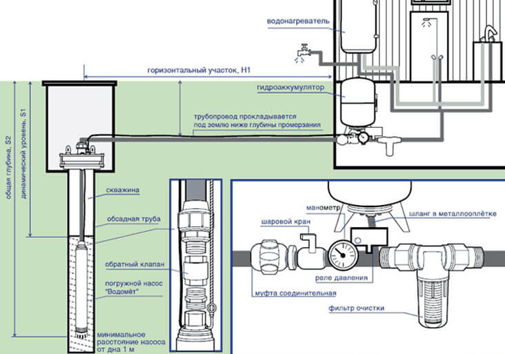
For uninterrupted supply, automation is required, which will monitor the water supply system and trouble-free operation.
The minimum set for supplying water from a well or well consists of:
- submersible pump;
- check valve;
- float with sensor;
- pressure switch;
- accumulator tank;
- electronic control unit.
Consider the purpose of these elements.
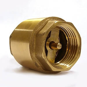
The pump is the main power element that produces the rise of water from the well. The non-return valve is a bypass membrane, which is installed directly at the output of the power unit, preventing the backflow of fluid from the pipe.
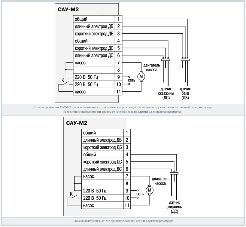
A float sensor is an automation element that monitors the water level in a well. It depends on its position whether permission to start the motor will be given or not. Also often, instead of a float, an electrode level sensor is installed. The sensor connection diagram is provided below:
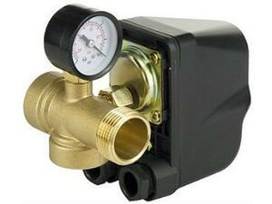
The pressure switch is another automation element that directly controls the start-up of a submerged unit and responds to changes in pressure in the water supply.
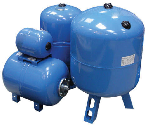
The hydraulic accumulator is a passive pressure support system in the pipe, smoothing out sudden surges and pressure drops. Works in tandem with a pressure switch. It extends the life of the pump by increasing the on and off times of the engine by accumulating water in the tank.
We figured out the elements of the system, now we will talk in more detail about how to connect the submersible pump to the automation.
Installation procedure for the water system
The location of the devices should provide access for maintenance and control of the operating mode. It is imperative to provide for ease of replacement of non-working parts. Take care in advance of rain and frost protection. To connect the submersible pump to the mains, it is necessary to use a special cable with the marking of the runway or HFB.The insulation of these wires is designed for a long time in water, without loss of flexibility and insulating properties. Imported analogue is marked AQUA RN8.
We recommend connecting the well pump to electricity via RCDrequired to control the insulation of the included devices and cable.After all, a timely identified and resolved problem is the saved budget and the nerves of the head of the family.
To install the pump and empty the pipes we need:
- the water-lifting unit itself;
- special tank - accumulator;
- pressure switch, choose under the tank capacity of the accumulator;
- American coupling for connecting a pressure switch to a hydraulic accumulator;
- collet coupling, for transition from size to size;
- brass adapters;
- fittings, plastic pipes, FUM tape.
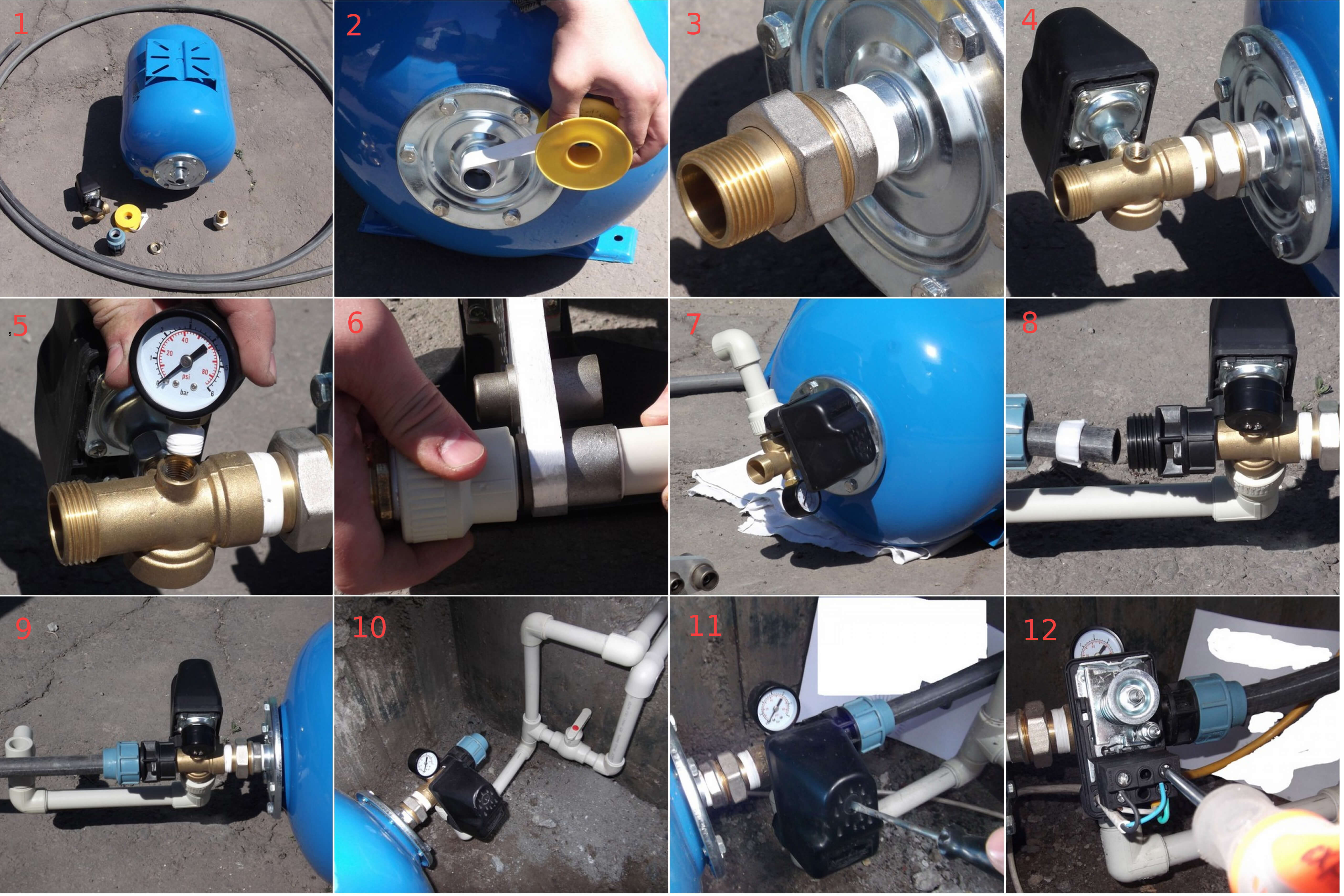
As a rule, installation and connection of a submersible pump begin to be carried out, starting with the tying of the accumulator, a set of equipment on it. All assembly steps are presented in order in the photo:
The first step is the preparation process. In the second picture of the FUM tape we produce a winding of a threaded connection. Next, we install the “American” connection, which allows for further simple assembly and disassembly. The fourth and fifth pictures show the installation of a pressure switch and pressure gauge for visual monitoring of the process in the system. After this stage, the process of mounting the outgoing elbow from the PVC pipe to the tee with sensors is demonstrated. The eighth and ninth photos show the installation of a collet clamp and a pressure pipe for supplying water. The tenth picture shows the installed group connected to the water supply. Well, the last steps are opening and connecting to the relay unit.
If your system will consist of one automation unit, a pressure sensor, then the LINE input and the MOTOR output are designated on the terminals of this device. That is, the input from the LINE outlet and the connection of the MOTOR submersible pump. More advanced automation consists of an electronic unit.
The pump start control unit provides uninterrupted water supply to the system, protecting the engine from dry running, reacting to the presence and level of water around the pump. The unit makes a soft start and a soft stop, prolonging the engine's engine life, monitors the mode of its operation.
Control unit diagram:
Dry running is the operation of the engine without enough water or without it, which causes overheating of the working windings of the engine, destruction of insulation, failure of the motor. All because water in the deep pumps plays the role of a cooler, because passes through it and cools the case.
Finally, we recommend watching a video that demonstrates the assembly technology of a system for increasing water pressure, as well as the installation process of a submersible pump in a well:
So we have provided step-by-step instructions for connecting a submersible pump to the network and the water supply system. As you can see, it’s not too difficult to do everything yourself, the main thing is to have a suitable installation diagram at hand, as well as to know some of the nuances that we talked about in this article!
It will be interesting to read:

