How to connect a pulse relay

Such switches can be controlled using the button with the NO return return, i.e., the circuit occurs only when it is pressed, as on the bell button.
Before designing a circuit, it is worthwhile to clarify the possibility of connecting buttons with a backlight, since not all models are able to work with them and perceive them as a switch in the closed position.
The number of buttons to control is not limited by anything, only common sense. The installation of a pulse relay is conveniently carried out in the bedside zone, in long corridors, in places with several entrances, entrances and front doors.

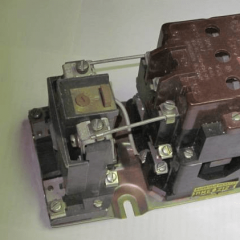
Some manufacturers make combined devices with a timer (as in the photo below), which returns to the off state after a user-specified time. This device is great for controlling lighting in an apartment building. Saving electricity and lamp life, forcibly turning off the lighting when there is no need for it.

The general scheme of connecting one relay to three buttons, which allows you to control the light from several places:
 As can be seen from the diagram, the load is connected to the gap of the neutral wire, between N and terminal 1. The phase wire is connected directly to terminal input 2. The pulse switch is controlled through terminals A1 and A2. The phase through the contacts of the buttons goes to terminal A1 and goes to the neutral wire from terminal A2.
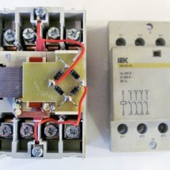
Due to their small size, bistable relays allow their installation not only in lighting panels and metering boxes, but also in hidden distribution boxes. This allows you to assemble the circuit directly at the lighting unit, saving material and human resources.
The video below clearly shows the connection diagrams of a pulse relay:
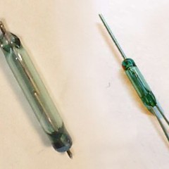
It is worth paying attention that mechanical impulse relays incorrectly work out switching in the “on the side” position, and this is due to design features. For electronic devices, their position in space does not affect performance. Consider this nuance if you want to install the device yourself.
If the room is large and more than one bistable switch is installed in it and the buttons are zoned apart over a large distance, special devices with additional control contacts Y1 and Y2, which have the highest priority over the main one, have been developed to control the lighting group.

According to the scheme, when a control signal is input to Y1, devices connected in parallel according to this scheme will turn on regardless of the previous state. When a signal is applied to Y2, a general shutdown will occur, again, regardless of the state that preceded it.
In this video, the connection diagram of the RIO-1 bistable relay is more clearly discussed:
Here, in fact, using this technique, the installation and connection of a pulse relay for lighting control is performed. If you have any questions, you can ask them in the comments under the article!
We also recommend reading: