How to connect a three-phase voltage regulator?
Mounting diagrams
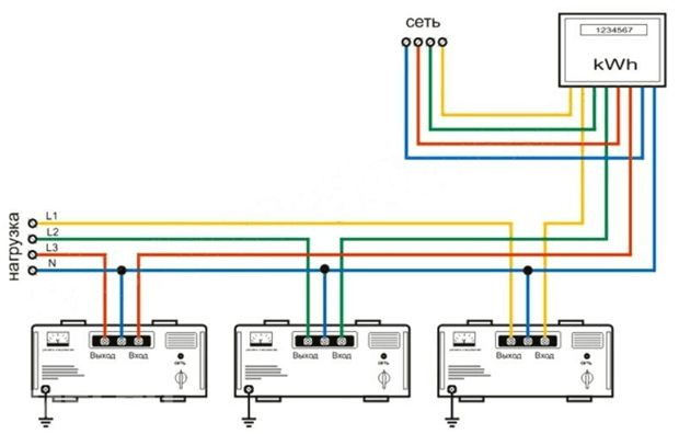
Structurally, a three-phase stabilizer, designed for a voltage of 380 volts, consists of three single-phase devices, each of which stabilizes a single-phase voltage. The connection of a stabilizer operating in a three-phase network should be carried out strictly in accordance with the attached instructions, which must be carefully studied before starting installation. According to the connection method, there are two types of devices. The circuit diagram for these devices has differences. The three-phase stabilizer of the first type contains three modules with three terminals to which the wires are connected. Connect the input and output of the phase wire to these terminals, as well as the neutral wire, which is common for power input, three stabilization modules, and load power circuits. Each module is connected to a single-phase network. A diagram illustrating the connection of this type of device is shown below:
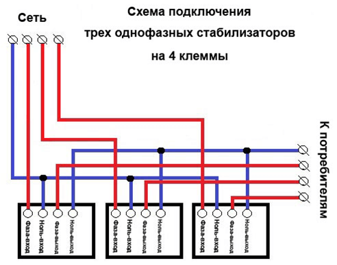
A three-phase stabilizer for voltage of 380 volts of the second type also contains three single-phase stabilizers, each of which has four terminals for connecting wires. In addition to the input and output of the phase wire, the input and output of the neutral wire should also be connected to the stabilizer modules of this type. Thus, in this circuit, the neutral wire of the power input is not connected to the neutral wire of the stabilized electrical network. The connection of this type of stabilizer is shown in the diagram below. The phase wires are red, the neutral wires are blue.
We also recommend that you watch the video on which the connection diagram of the voltage regulator to the 380 Volt network is provided:
General Connection Rules
After unpacking, the three-phase voltage stabilizer must be inspected and checked for mechanical and other damage before unpacking. If the product was transported at a negative temperature, the device should be kept in the room where it will be installed, the necessary amount of time for the ice to disappear, and the condensate on the parts will evaporate.
The device must be connected by a qualified person. If the instructions set out the requirements for the personnel making the connection, they should be observed. The requirements, as a rule, are the availability of certification for a certain electrical safety group. The connection of the three-phase stabilizer itself must be carried out in strict accordance with the electrical circuit attached to the product.
First, the stabilizer is installed in the place where it will function. The device must be installed in a dry room where it will not be exposed to conductive dust. During operation, air should be provided to the ventilation openings in the casing of the device for normal cooling of the electrical elements that contain the stabilizer circuit. The environment in the place where the stabilizer is installed must not contain aggressive substances that can destroy the insulation and metal parts of the device. The range of ambient temperature, atmospheric pressure and humidity should correspond to the values specified in the instruction manual. It must be remembered that violation of the conditions of installation and operation entails a refusal of warranty repair and maintenance.
The connection of the input power circuits through which the mains voltage is supplied must be made through the switch (circuit breaker), the rated current of which is selected according to the load current connected to the stabilizer. The circuit breaker must provide protection against short circuits by current cutoff, as well as protection against overload current, having a time delay.
Protective earth circuits made in accordance with the EMP must be connected to the terminal intended for this purpose. A three-phase stabilizer for a voltage of 380 volts can only function normally if there is a neutral wire, that is, the electrical network supplied to the device must be four-wire. The cross section of the conductors that connect the input circuits, as well as the stabilized outputs, must be selected according to the load current. To do this, you can use the table from the PUE. About, how to calculate the cable cross section for current, we told in a separate article.
Finally, we recommend that you watch the video, which clearly shows the general rules for installing CH:
Here, according to such instructions, a three-phase voltage stabilizer for the house is connected. We hope that the provided tips and installation diagrams have helped you sort out the issue!
It will be useful to read:

