How to independently connect a thermal relay - overview of schemes
What is important to know?
In order not to repeat, and not to pile up extra text, I will briefly outline the meaning. A current relay is an essential attribute of a drive control system. This device responds to the current that passes through it to the motor. It does not protect the motor from a short circuit, but only protects it from working with high current arising from overload or abnormal operation of the mechanism (for example, a wedge, jamming, mashing and other unforeseen moments).
When choosing a thermal relay, they are guided by the passport data of the electric motor, which can be taken from the plate on its case, as in the photo below:

As can be seen on the tag, the rated current of the electric motor is 13.6 / 7.8 Amperes, for voltages of 220 and 380 Volts. According to the operating rules, a thermal relay must be selected 10-20% more than the nominal parameter. The ability of the heater to work on time and prevent damage to the electric drive depends on the correct choice of this criterion. When calculating the installation current for the rating on the tag at 7.8 A, we got a result of 9.4 Amps for the current setting of the device.
When choosing in the product catalog, you need to take into account that this rating was not extreme on the scale for adjusting the setpoint, so it is advisable to choose a value closer to the center of the adjustable parameters.For example, as on the RTI-1314 relay:

Mounting Features
As a rule, the installation of a thermal relay is carried out together with magnetic starter, which carries out switching and starting the electric drive. However, there are also devices with the possibility of installation as a separate device next to the mounting plate or DIN railsuch as TRN and PTT. It all depends on the availability of the desired face value in the nearest store, warehouse or garage in “strategic stocks”.

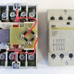
 The presence of a TRN thermal relay with only two incoming connections should not scare you, since there are three phases. An unconnected phase wire goes from the starter to the motor, bypassing the relay. The current in the electric motor varies proportionally in all three phases, so it is enough to control any two of them. The assembled design, the starter with a TRN heating plug will look like this:
 Or so with PTT:

The relays are equipped with two groups of contacts normally closed and normally open group, which are signed on the housing 96-95, 97-98. In the picture below, the structural designation scheme according to GOST: Let's figure out how to assemble a control circuit that would disconnect the engine from the network in the event of an emergency overload or phase failure. From our article about motor connection via magnetic starter, you already learned some nuances. If you have not had time to familiarize yourself then just follow the link.
Consider the scheme from the article in which the three-phase motor rotates in one direction and the start-up is controlled from one place by two STOP AND START buttons.

The machine is turned on and voltage is supplied to the upper terminals of the starter. After pressing the START button, the starter coil A1 and A2 is connected to the network L2 and L3. In this scheme, a starter with a 380 volt coil is used, look for a connection option with a 220-volt single-phase coil in our separate article (link above).
The coil turns on the starter and the additional contacts No. (13) and No. (14) are closed, now you can release the START, the contactor will remain on. This circuit is called a “self-pick-up start”. Now, in order to disconnect the engine from the network, it is necessary to disconnect the coil. Having followed the current path according to the scheme, we can see that this can happen when STOP is pressed or the contacts of the thermal relay open (highlighted in red).
That is, in the event of an emergency, when the heater works, it will break the circuit and remove the starter from the self-pickup, disconnecting the motor from the mains. When this current monitoring device is triggered, before restarting, it is necessary to inspect the mechanism to find out the cause of the trip, and not turn it on until it is eliminated. Often the cause of the operation is the high external temperature of the ambient air, this moment must be taken into account when operating the mechanisms and setting them up.
The scope of application of thermal relays in the household is not limited only to home-made machines and other mechanisms. It would be correct to use them in the current control system of the heating pump. The specificity of the circulation pump is that limescale forms on the blades and the cochlea, which can cause the motor to jam and break down. Using the above connection diagrams, it is possible to assemble a pump control and protection unit. It is enough to install the desired heat rating in the power circuit and connect the contacts.
In addition, it will be interesting to connect a thermal relay through current transformers for powerful engines, such as a watering system pump for holiday villages or farms.When installing transformers in the power circuit, the transformation coefficient is taken into account, for example 60/5, when the current through the primary winding is 60 amperes, it will be 5A on the secondary winding. The use of such a scheme allows you to save on components, while not losing in operational characteristics.

As you can see, the current transformers are highlighted in red, which are connected to the control relay and ammeter for visual visibility of the processes. Transformers are connected by a star circuit, with one common point. Such a scheme does not constitute great difficulties in implementation, so you can assemble it and connect it to the network yourself.
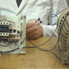
Finally, we recommend watching a video that clearly shows the process of connecting a thermal relay to a magnetic starter to protect the motor:
That's all you need to know about connecting a thermal relay with your own hands. As you can see, the installation is not particularly difficult, the main thing is to correctly draw up a connection diagram of all the elements in the circuit!
It will be interesting to read:


There are two pairs of contacts on the heating pad, we will put a coil on one pair, and the second pair for which
One pair of contacts NO (normally open) and NC (normally closed), depending on which circuit, you choose which pair of contacts you will use.
To all salams! Who knows, here I can’t understand how to protect e-mail. 45 kW with current transformers. Well, let's say this engine and it has a nominal value of 84 amperes, I take TT 100/5 and connect it through tr to 4 amperes per ammeter ?????? Who knows, tell me, I can’t find the circuit.
THANKS. BRIEFLY CLEAR.