What is a short-circuit breaker?
Operating principle
A transformer is a device that is an electromagnetic device with 2 (or more) windings. This device is intended mainly for converting alternating current from one voltage to another. The transformation of energy occurs due to the magnetic field. Transformer booths in the main part are used to conduct electricity over long distances, while all this is shared and sent to receivers, rectifiers, amplifiers of various types of devices. The main component of the above device is a wire with windings. For high-quality operation, transformers are equipped with short-circuiting and separators that regulate the health of the device.
Briefly about the short circuit
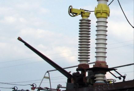
Short circuit – it is a device that creates unnatural in electric lines short circuit. Where are such devices used? First of all, the device is installed in transformers. It is used to shut down a faulty transformer after a short circuit has been created during relay protection actions the line that feeds. After that, both the transformer and the line are disconnected from the mains.
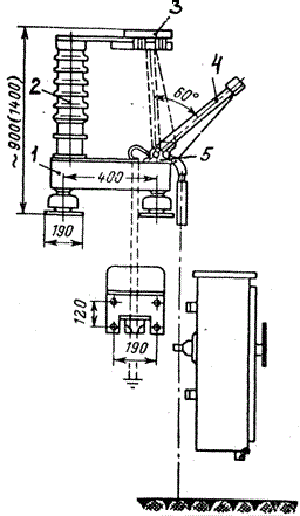
How does the short circuiter work? The device works on 2 or 1 pole, depending on the voltage. Installations having 35 kV operate with two poles, and with a voltage of 110 kV or more, one pole is used. You can visually consider the photo and circuit of the short circuit to understand what it consists of.
Short-circuit circuit KZ-35: (1 - steel box; 2 - support insulator; 3 - immovable contact; 4 - moving grounded knife (contact); 5 - shaft).
The short-circuit gear has a spring, which is responsible for turning on the moving knife to an immovable contact, which is currently energized. Relay protection gives an impulse, starting the drive, but trips manually. To avoid the occurrence of an arc and breakage of the device, it is necessary to increase the playfulness of the knife. In such constructions, the short circuit closes in 0.15 - 0.5 s.
Briefly about the separator
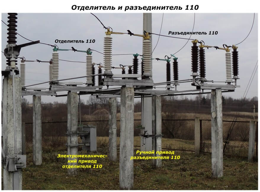
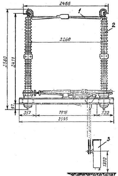
The separator is a kind of disconnector, quickly disconnecting the network without current when the team goes about it. It can be distinguished from the disconnector thanks to a spring-shaped actuator located on the separator. The inclusion of this device is carried out manually.Separators can also have a grounded leg on one side or on both. Consider in the photo and diagram below what the separator consists of:
The scheme of the separator OD – 220: (1 - 2-column disconnector with a knife that rotates; 2 - columns; 3 - actuator in the form of springs).
After familiarizing yourself with the circuit, let's see how the separator works. It disconnects the circuit (without current) or the magnetization current, but it is impossible to disconnect the short circuit current that appeared during the start of the short circuit. And through this nuance, there is a blockage in the OD and KZ circuits, which does not allow the separator to turn off, provided that a current passes through the transformer. Where is this device used? In a transformer box, to stabilize its operation.
Also, so that the separator does not disconnect, a current relay is introduced into the design, which is connected directly to the current transformer located in the short circuit. After disconnecting the line, the relay closes the contact and the capacitor, which will lead it to work. Further, thanks to the capacitor 2, a trip will occur.
Teamwork
If the design is open, then the operation of the aforementioned devices is unstable (up to the refusal to work), since they are sensitive to frost and ice. For this reason, closed gas chambers have been developed. Gas can leak and, under this condition, it is recovered from the cylinder, which is attached to the shell of the chamber. The pressure in such chambers is constantly regulated by a manovacuum meter.
The short-circuit breaker contains a contact chamber made of porcelain and 2 electrodes with a single gap of 0.9 cm. There is an output for attaching a bus conducting current in an immovable contact. Flexible connections connect the contact. The contact chamber is filled with gas with a pressure of 0.3 MPa. The gas in the chamber cannot be burned, and this does not pose a risk of explosion or fire. Based on this device for extinguishing the arc do not make sense in the design. The bottom contact is similar to a rod with a cylinder in the form of a screen and has a socket type.
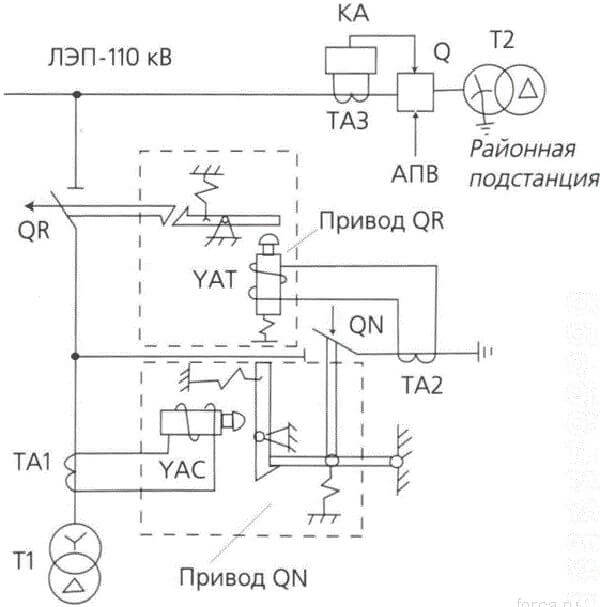
The collaboration scheme looks like this:
Where:
- Q - switch;
- QR - separator;
- QN - short circuit;
- T1, T2 - power transformers;
- TA1, TA2, TA3 - current transformers;
- YAT - shutdown of a separator;
- YAC - short circuit enable.
This system, the combination is almost analogous to a high voltage circuit breaker. In an emergency situation inside the zone that is being protected, the power transformer acts as a protective element, which, using some processes, de-energizes all consumers of this transformer.
Also during a time when there is no current supply, the separator is switched off to prevent its own breaking from current exposure. Such a system is used in high current networks. As we said above, the OD-KZ system is cheap, but nowadays it is already outdated and is being replaced by newer switches. You can learn more about this issue by watching the video:
Advantages and disadvantages
Open separators and short-circuiting switches do not work very well in adverse weather conditions. Because of this, a certain design with a contact system was created, placed in a chamber with SF6 gas.
A 35 kilowatt installation uses 2 poles. More powerful (110 kilowatts or more) uses one pole. Typical short circuits operate for a very long time and therefore it is more advisable to use a device based on a powder charge. Its explosion starts the knife in motion.
It is important to know that when monitoring the condition of devices, first of all, you need to check the insulation on all parts.
That's all I wanted to tell you about the principle of operation, design and purpose of short circuits and separators. We hope the information was useful and understandable to you!
We also recommend that you read:

