What is a DC commutator motor and how does it work
Collector motors are quite common in everyday life and in production. They are used to drive various mechanisms, power tools, in cars. Part of the popularity is due to the simple adjustment of the rotor speed, but there are some limitations to their use and, of course, disadvantages. Let's look at what a direct current collector motor (KDTT), what are the varieties of this type of electric motor and where they are used.
Definition and device
In directories and encyclopedias lead, such a definition:
“A collector motor is called an electric motor, in which the shaft position sensor and the switch of the windings are the same device - the collector. "Such engines can operate either only on direct current or on direct and alternating current.”
A collector motor, like any other, consists of rotor and stator. In this case, the rotor is an anchor. Recall that the anchor is the part of the electric machine that consumes the main current, and in which the electromotive force is induced.

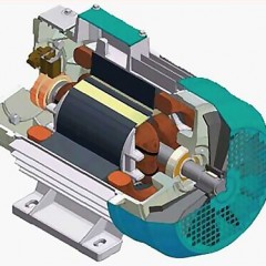
Why is it needed and how is the collector arranged? The collector is located on the shaft (rotor), and is a set of longitudinally located plates isolated from the shaft and from each other. They are called lamellas. The bends of the sections of the armature windings are connected to the lamellas (you can see the KDPT anchor winding device in the group of figures below), or rather, the end of the previous and the beginning of the next winding section are connected to each of them.

The current is supplied to the windings through the brushes. The brushes form a sliding contact and during rotation of the shaft are in contact with one or the other lamella. Thus, the windings of the armature are switched, for this the collector is needed.
The brush assembly consists of an arm with brush holders, and graphite or metallographite brushes are installed directly in them. To ensure good contact, the brushes are pressed against the collector by springs.
Permanent magnets or electromagnets are installed on the stator (field winding), which create a stator magnetic field. In the literature on electric machines, the terms “magnetic system” or “inductor” are more often used instead of the word “stator”. The figure below shows the design of the DPT in different projections. Now let's see how the DC commutator motor works!

Operating principle
When the current flows through the armature winding, a magnetic field appears, the direction of which can be determined using gimlet rules. The constant magnetic field of the stator interacts with the field of the armature, and it begins to rotate due to the fact that the poles of the same name repel, attracted to the unlike ones. Which is perfectly illustrated by the figure below.

When the brushes switch to other lamellas, the current begins to flow in the opposite direction (if we consider the above example), the magnetic poles change places and the process repeats.
In modern collector machines, a two-pole design is not used due to uneven rotation, at the moment of switching the direction of the current, the forces acting on the armature will be minimal. And if you turn on the engine, the shaft of which stopped in this "transitional" position - it may not start to rotate at all. Therefore, the collector of a modern DC motor has significantly more poles and sections of windings laid in the grooves of the lined core, thus achieving optimal smoothness of movement and torque on the shaft.
The principle of the operation of the collector engine in simple language for dummies is disclosed in the next video, we strongly recommend that you read it.
KDPT types and windings connection schemes
According to the method of excitation, DC collector motors are of two types:
- With permanent magnets (low-power motors with power of tens and hundreds of watts).
- With electromagnets (powerful machines, for example, on hoisting mechanisms and machine tools).
Distinguish these types of KDTT by the method of connecting the windings:
- Sequential excitation (in the old Russian literature and from old electricians you can hear the name "Serial", from the English Serial). Here, the field winding is connected in series with the armature winding. A high starting torque is the advantage of such a scheme, and its disadvantage is a drop in the rotational speed with increasing load on the shaft (soft mechanical characteristic), and the fact that the engine is peddling (uncontrolled increase in speed with subsequent damage to the thrust bearings and armature) if idling or with a shaft load of less than 20-30% of the nominal.
- Parallel (also called "shunt"). Accordingly, the field winding is connected in parallel with the armature winding. At low speeds on the shaft, the torque is high and stable in a relatively wide range of revolutions, and with an increase in revolutions it decreases. The advantage is stable revolutions over a wide range of load on the shaft (limited by its power), and the disadvantage is that if the circuit breaks in the excitation circuit, it can go awry.
- Dependent. Field windings and anchors are powered by different sources. This solution allows you to more accurately control the shaft speed. Features of work are similar to DPT with parallel excitation.
- Mixed. Part of the field winding is connected in parallel, and part in series with the armature. Combine the advantages of serial and parallel types.


The graphic symbol on the diagram you see below.

In foreign and modern Russian literature, as well as on diagrams, one can find another representation of UGO for KDT, as was shown in the previous figure in the form of a circle with two squares, where the circle represents the anchor and two squares represent the brushes.
Connection diagram and reverse
The connection diagram of the stator and rotor windings is determined during manufacture, and, depending on where a particular motor is used, you need to choose the appropriate solution. In certain operating modes (braking mode, for example), the winding switching circuits may change or introduce additional elements.
They include low-power DC collector motors using: semiconductor keys (transistors), toggle switches or buttons, specialized driver microcircuits, or using low-power relays. Large powerful machines are connected to the DC network via bipolar contactors.
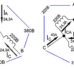
Below you see a reverse circuit for connecting a DC motor to a 220V network. In practice, the circuit will be similar in production, but there will be no diode bridge in it, since all lines for connecting such motors are laid from traction substations, where the alternating current is rectified.

The reverse is carried out by changing the polarity on the field winding or on the armature. It is impossible to change the polarity both there and there, since the direction of rotation of the shaft will not change, as is the case with universal collector motors when operating on alternating current.
To smoothly start the engine, an adjusting device, for example, a rheostat, is introduced into the power supply circuit of the armature winding or the armature winding and the excitation winding (depending on the circuit of their connection), but the shaft speed is also controlled in the same way, but instead of a rheostat, they often use a set of constant resistors connected using a set of contactors.

In modern applications, the rotational speed is changed using pulse-width modulation (PWM) and a semiconductor key, which is exactly what is done in a cordless power tool (a screwdriver, for example). The efficiency of this method is much higher.

Scope of application
DC brush motors are used everywhere both in everyday life and in industrial devices and mechanisms, let's briefly consider their scope:
- In cars, 12V and 24V collector DCBs are used to drive wiper blades (windshield wipers), in window lifters, to start the engine (a starter is a series or mixed excitation DC collector motor) and other drives.
- In hoisting mechanisms (cranes, elevators, etc.) are used KDPT, which operate on a DC network with a voltage of 220V or any other available voltage.
- In children's toys and low-power radio-controlled models, KDTT with a three-pole rotor and permanent magnets on the stator are used.
- In a manual cordless power tool - a variety of drills, grinders, electric screwdrivers, etc.
Note that in a modern expensive power tool, brushless motors are installed, but brushless motors.
Advantages and disadvantages
Let's analyze the pros and cons of a DC collector motor. Benefits:
- The ratio of size to power (weight and size indicators).
- Simplicity of adjustment of turns and implementation of soft start.
- Starting torque.
The disadvantages of KDPT are as follows:
- Worn brushes. Highly loaded engines that are regularly used require regular inspection, brush replacement and maintenance of the manifold assembly.
- The collector wears out due to friction of the brushes.
- Brush sparking is possible, which limits the use in hazardous places (then use KDTT explosion-proof execution).
- Due to the constant switching of the windings, this type of DC motor introduces interference and distortion into the supply circuit or mains, which leads to malfunctions and problems in the operation of other circuit elements (especially relevant for electronic circuits).
- With permanent magnet magnets, the magnetic forces weaken (demagnetize) over time and the efficiency of the motor decreases.
So we examined what a DC brush motor is, how it is designed and what its operating principle is. If you have questions, ask them in the comments under the article!
Related materials: