What is a brushless DC motor, how is it built and running
Definition
A brushless DC motor is called a DC motor, the current in the windings of which is switched by a special switch device - it is called the “driver” or “inverter” and these windings are always located on the stator. The switch consists of 6 transistors, they supply current to a particular winding, depending on the position of the rotor.
In domestic literature, such motors are called “valve” (because semiconductor switches are called “valves”), and there is a separation of such electric machines into two types in the form of counter-EMF. In foreign literature, such a difference persists, one of them is called analogously to the Russian “BLDC” (brushless direct current drive or motor), which literally sounds like “brushless DC motor” in their windings a trapezoidal EMF appears. Valve motors with a sinusoidal EMF are called PMSM (Permanent magnet synchronous machine), which translates as "synchronous electric motor with excitation by permanent magnets."
The device and principle of operation
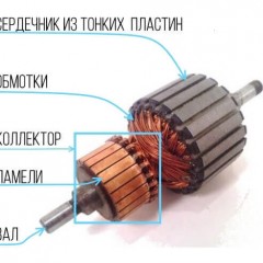
The collector in the KDPT serves as a node for switching current in the armature windings. In a brushless DC motor (BDT), this role is played not by lamella brushes, but by the commutator of it by semiconductor switches - transistors. Transistors switch the stator windings, creating a rotating magnetic field that interacts with the field of rotor magnets. And when current flows through a conductor that is in a magnetic field, it acts on it Ampere force, due to the action of this force, a torque is generated on the shaft of electric machines. The principle of operation of any electric motor is based on this.
 and the brushless motor (right)")
Now let's figure out how the brushless motor works. 3 windings are usually located on the BDPT stator, by analogy with AC motors they are often called three-phase. This is partly true: brushless motors run on a direct current source (often from batteries), but the controller turns on the windings alternately. However, it is not entirely true to say that alternating current flows through the windings. The final shape of the supply voltage winding is formed by rectangular transistor control pulses.
A three-phase brushless motor can be three-wire or four-wire, where the fourth wire is a tap from the midpoint (if the windings are connected along star pattern).

Windings or, in simple words, coils of copper wire fit into the teeth of the stator core. Depending on the design and purpose of the drive, the stator may have a different number of teeth. There are different options for the distribution of phase windings along the teeth of the rotor, as illustrated in the following figure.

The windings of each of the teeth within one phase can be connected in series or in parallel, depending on the tasks assigned to the designer in terms of power and the moment of the designed drive, and the windings of the phases themselves are interconnected according to the pattern of a star or a triangle, like asynchronous or synchronous three-phase AC motors.

Rotor position sensors can be installed in the stator. Hall sensors are often used, they give a signal to the controller when they are affected by the magnetic field of the rotor magnets. This is necessary in order for the controller to “know” in what position the rotor is and to supply power to the corresponding windings. This is necessary to increase the efficiency and stability of the work, and in short, to squeeze out all the possible power from the engine. Sensors usually installed 3 pieces. But the presence of sensors complicates the device of a brushless motor, they need to conduct additional wires for power and data lines.

In the BDTT, permanent magnets mounted on the rotor are used for excitation, and the stator is an anchor. Recall that in collector machines it is the other way around (the rotor is an anchor), and for excitation in the CD, both permanent magnets and electromagnets (windings) are used.
The magnets are mounted with alternating poles, and accordingly their number determines the number of pairs of poles. But this does not mean that how many magnets, then as many pairs of poles. Several magnets can form one pole. The number of revolutions per minute depends on the number of poles, as is the case with an induction motor (and others). That is, from one controller on the same settings, brushless motors with a different number of pole pairs will rotate at different speeds.

Types of BDTT
Now let's see what brushless permanent magnet motors are like. They are classified by the shape of the counter-EMF, design, as well as by the presence of rotor position sensors. So, there are two main types that differ in the form of counter-EMF, which is induced in the windings when the rotor rotates:
- BLDC - in them a trapezoidal anti-EMF;
- PMSM - anti-emf sinusoidal.
Ideally, they need different power sources (controllers), but in practice they are interchangeable. But if you use a controller with a rectangular or trapezoidal output voltage with a PMSM motor, you will hear characteristic sounds, similar to a knock during rotation.
And by design, brushless DC motors are:
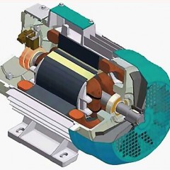
- With an internal rotor. This is a more familiar representation of the electric motor, when the stator is a body, and the shaft located in it rotates. Often they are called the English word "Inrunner". This option is usually used for high-speed electric motors.
- With an external rotor. Here the outer part of the engine rotates with a shaft fixed to it; in English sources it is called “outrunner”. This device circuit is used when you need a high moment.
The design is chosen depending on why a brushless motor is needed in a particular application.
 and outrunner (right)")
Modern industry produces brushless motors with and without rotor position sensors. The fact is that there are many ways to control the BDTT, for some of them position sensors are needed, others determine the positions by EMF in the windings,the third ones simply supply power to the necessary phases and the motor independently synchronizes with such power supply and enters the operating mode.
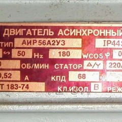
Main characteristics of brushless DC motors:
- Operating mode - long or short.
- Maximum operating voltage.
- Maximum working current.
- Maximum power.
- The maximum revolutions, often indicate not revolutions, but KV - r / v, that is, the number of revolutions per 1 volt of the applied voltage (without load on the shaft). To get the maximum speed - multiply this number by the maximum voltage.
- The resistance of the winding (the smaller it is, the higher the efficiency), usually amounts to hundredths and thousandths of Ohm.
- The phase advance angle (timing) is the time after which the current in the winding reaches its maximum, this is due to its inductance and switching laws (the current in the inductance cannot change instantly.
Wiring diagram
As mentioned above, for the operation of a brushless motor you need a special controller. On aliexpress, you can find both kits from the engine and controller, or separately. The controller is also called the ESC Motor or Electric Speed Controller. They are selected by the strength of the current given to the load.
Usually connecting the electric motor to the controller is straightforward and is understandable even for dummies. The main thing you need to know is that in order to change the direction of rotation, you need to change the connection of any two phases, in fact as well as in three-phase asynchronous or synchronous motors.

The network has a number of technical solutions and schemes, both complex and for dummies, which you can see below.
In this video, the author tells how to make friends with the motor BC "Arduino".
And in this video you will learn about different ways to connect to different controllers and how you can do it yourself. The author demonstrates this with an example of a motor from HDD, and a pair of powerful instances - inrunner and outrunner.
By the way, we also apply the diagram from the video for repetition:

Where brushless motors are used
The scope of such electric motors is ahead of schedule wide. They are used both for driving small mechanisms: in CD drives, DVD drives, hard drives, and in powerful devices: a battery and a power tool (with a power supply of about 12 V), radio-controlled models (for example, quadrocopters), CNC machines for driving a working body (usually motors with a rated voltage of 24V or 48V).
BDTTs are widely used in electric vehicles, almost all modern motor-wheels of electric scooters, bicycles, motorcycles and cars are brushless motors. By the way, the rated voltage of electric motors for transport lies in a wide range, for example, the bicycle wheel motor often runs from 36V or 48V, with rare exceptions and more, and in cars, for example, the Toyota Prius is about 120V, and on the Nissan Leaf - comes to 400, while charging from a 220V network (this is implemented using the built-in converter).
In fact, the scope of brushless electric motors is very extensive, the absence of a collector node allows it to be used in dangerous places, as well as in places with high humidity, without fear of short circuits, sparking or fire due to defects in the brush assembly. Due to their high efficiency and good overall dimensions, they have found application in the space industry.
Advantages and disadvantages
Brushless DC motors, like other types of electric machines, have certain advantages and disadvantages.
The advantages of the BDTT are as follows:
- Thanks to excitation by powerful permanent magnets (neodymium, for example), they are superior in torque and power and have smaller dimensions than induction motors. What is used by most electric vehicle manufacturers - from scooters to cars.
- There is no sparking brush collector assembly that requires regular maintenance.
- When using a high-quality controller, unlike the same CD, they do not interfere with the power supply network, which is especially important in radio-controlled devices and vehicles with advanced electronic equipment in the on-board network.
- Efficiency more than 80, more often and 90%.
- High rotation speed, in some cases up to 100,000 rpm.
But there is a significant minus: a brushless motor without a controller is just a piece of iron with a copper winding. He will not be able to work. Controllers are not cheap and most often they have to be ordered in online stores or with aliexpress. Because of this, using BC motors in home-made models and devices is not always possible.
Now you know what a brushless DC motor is, how it works and where it is used. We hope our article helped you sort out all the issues!
Related materials:


Well, after all, there are people who not only know the material, but are also gifted by God with the ability to intelligently, intelligibly, and not bored to expose it!
I read like a cool detective!
Many thanks to the author for the article, every success and all the best in life!
👍👍👍👍👍👍👍👍👍👍👍👍👍👍
I agree with everything except one. On the prius is a regular asynchronous 17 kW at 380v battery gives 288 constant. Well, then a little electronics and let's go