How to charge for a car battery from a transformer
Sometimes it happens that the battery in the car does not sit down and start it, because the starter does not have enough voltage and, accordingly, current to crank the motor shaft. In this case, you can “light up” from another owner of the car so that the engine starts and the battery starts charging from the generator, however, this requires special wires and a person who wants to help you. You can also charge the battery yourself using a specialized charger, but they are quite expensive, and you do not have to use them very often. Therefore, in this article we will consider in detail the homemade device, as well as instructions on how to make a charger for a car battery with your own hands.
Homemade device
The normal voltage on a battery disconnected from the vehicle is between 12.5 V and 15 V. Therefore, the charger must provide the same voltage. The charge current should be equal to about 0.1 of the capacity, it may be less, but this will increase the charging time. For a standard battery with a capacity of 70-80 a / h, the current should be 5-10 amperes, depending on the specific battery. Our homemade battery charger must meet these parameters. To assemble the charger for the car battery, we need the following elements:
Transformer. We can use any of the old electrical appliances or bought on the market with an overall power of about 150 watts, it is possible more, but not less, otherwise it will become very hot and may fail. Well, if the voltage of its output windings is 12.5-15 V, and the current is about 5-10 amperes. You can see these parameters in the documentation for your part. If there is no necessary secondary winding, then it will be necessary to rewind the transformer to a different output voltage. For this:
- Remove all unnecessary secondary windings, leaving only the primary.
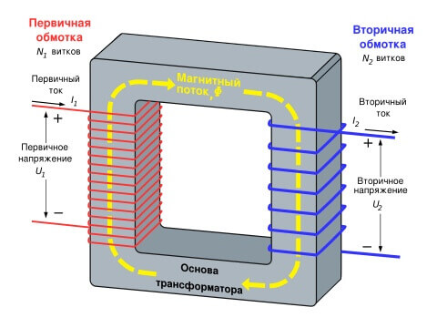
- Calculate the required number of turns and wire cross-section for the appropriate voltage and current. For this, there are special calculators and formulas from the physics course. The required wire diameter is calculated according to the table below. The wire must be in varnish insulation. And the number of turns is determined by the ratio: U1 / U2 = N1 / N2. It follows that if your primary winding consists of 480 turns, then to get 13 volts at the output you need to wind only 26 turns, since the mains voltage is 220 volts.

- After that, lay the wire on the basis of the coil to the coil, making the insulation between the layers of paper or electrical tape in several layers. The end and the beginning of the windings are removed and securely fixed to the housing. To solder the wires to them, strip the insulation with a knife.
- To reduce noise and vibration, as well as improve insulation, you can soak the device with paraffin.
Thus, we found or assembled the ideal transformer to make a charger for the battery with our own hands.
We will also need:
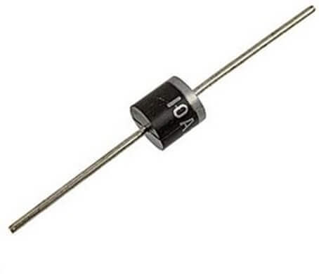
- 4 diodes. Any diodes with a current of at least 10 amperes will do. Some of the most popular: imported - 10A10, domestic - D242A, 2D203A, KD213B. Or diode bridges, for example: KVRS1001, KVRS1002 and their analogues.
- 4 radiators for diodes. You can, of course, do without them at low currents of the order of 3-5 Amps. But this can lead to their rapid failure, so radiators with an area of 32 square meters are needed. cm or 128 sq. cm for diode bridge. They can be made of sheet aluminum or use coolers from a computer and motherboards.
- Collapsible electrical plug or power cord.
- Copper wires with a cross section of at least 2.5 square meters. mm
- 0.5A and 10A fuses.
- Heat-shrink tubing or electrical tape.
- A dielectric plate, or even better, a body, such as plywood or plastic.
- A piece of nichrome wire from a hotplate.

- Multimeter or voltmeter with an ammeter.
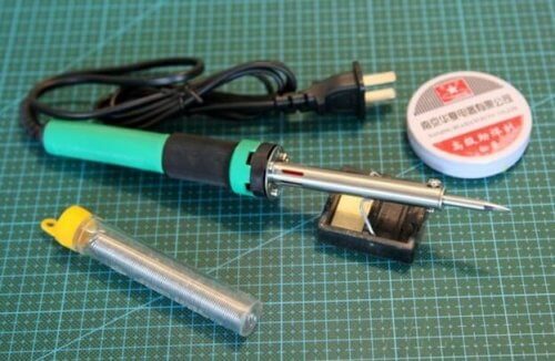
- Soldering iron, solder and flux (rosin or LTI-120).
- A few more radio components, if we want to make a device with protection and automatic shutdown.
Having prepared all the materials, you can proceed to the assembly process of the automobile memory itself.
Assembly technology
To make a charger for a car battery with your own hands, you must follow the step by step instructions:
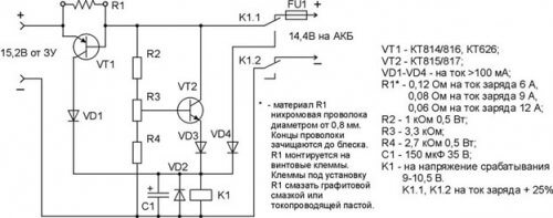
- We create a homemade charging scheme for the battery. In our case, it will look like this:
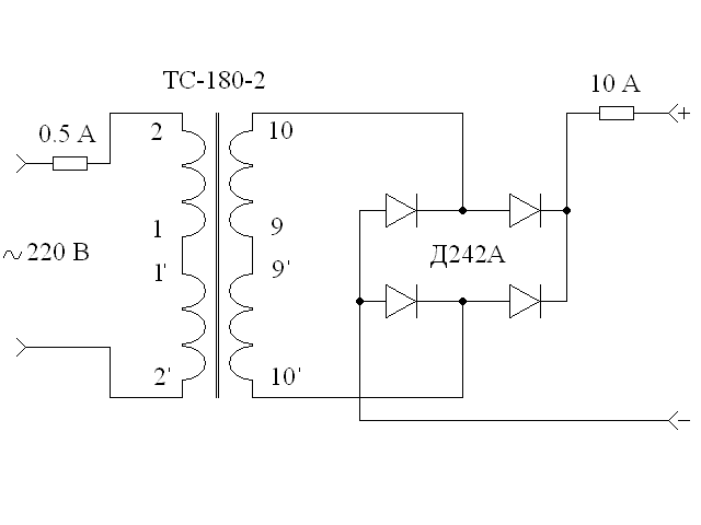
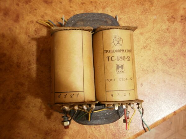
- We use the TS-180-2 transformer. It has several primary and secondary windings. To work with it, you need to connect two primary and two secondary windings in series to get the desired voltage and current at the output.
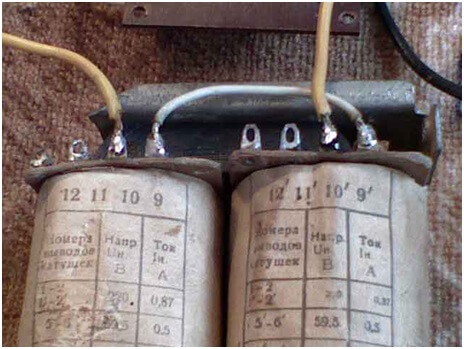
- Using copper wire, we connect conclusions 9 and 9 ’.
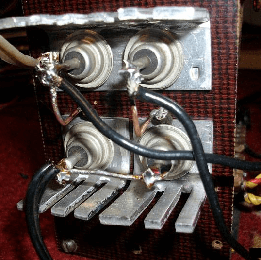
- On a fiberglass plate we assemble a diode bridge of diodes and radiators (as shown in the photo).
- Conclusions 10 and 10 ’are connected to the diode bridge.
- Between conclusions 1 and 1 ’we install a jumper.
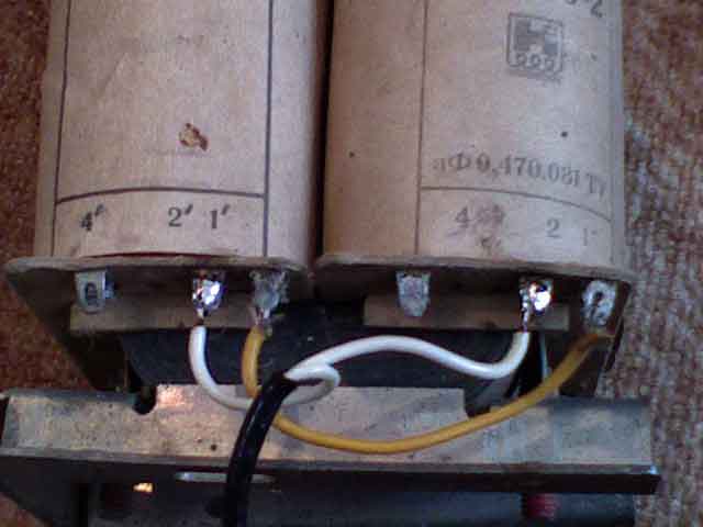
- To pins 2 and 2 ’, using a soldering iron, we attach the power cord with a plug.
- In the primary circuit we connect a 0.5 A, 10-amp fuse, respectively, to the secondary.
- In the gap between the diode bridge and the battery, we connect the ammeter and a piece of nichrome wire. We fix one end and the other should provide a movable contact, thus the resistance will change and the current supplied to the battery will be limited.
- We isolate all connections with heat shrink or electrical tape and put the device into the case. This is to avoid electric shock.
- We establish a movable contact at the end of the wire so that its length and, accordingly, the resistance are maximum. And connect the battery. Reducing and increasing the length of the wire, you need to set the desired current value for your battery (0.1 of its capacity).
- During charging, the current supplied to the battery will decrease itself, and when it reaches 1 ampere, we can say that the battery is charged. It is also advisable to directly control the voltage on the battery, however, for this it must be disconnected from the charger, since when charging it will be slightly higher than the actual values.
The first start-up of the assembled circuit of any power source or charger is always carried out through an incandescent lamp, if it lights up in full heat - or somewhere an error, or the primary winding is closed! An incandescent lamp is installed in the gap of the phase or neutral wire supplying the primary winding.
This circuit of a homemade battery charger for a battery has one big drawback - it does not know how to disconnect the battery from charging on its own after reaching the desired voltage. Therefore, you will have to constantly monitor the voltmeter and ammeter readings. There is a design devoid of this drawback, however, for its assembly will require additional details and more effort.
Terms of Use
The disadvantage of a homemade charger for a 12V battery is that after a full charge of the battery, the device does not automatically turn off. That is why you will have to periodically glance at the scoreboard in order to turn it off in time. Another important nuance - it is strictly forbidden to check the memory “for a spark”.
Among the additional precautions should be highlighted as follows:
- when connecting the terminals, be careful not to mix up “+” and “-”, otherwise a simple home-made battery charger for the battery will fail;
- connection to the terminals must be carried out only in the off position;
- the multimeter must have a scale of more than 10 A;
- when charging, unscrew the plugs on the battery, in order to avoid its explosion due to boiling of the electrolyte.
That, in fact, was all I wanted to tell you about how to make a charger for a car battery with your own hands. We hope that the instruction was understandable and useful for you, as This option is one of the simplest types of homemade charging for the battery!
Also read:




Everything is correct, but I remove all unnecessary windings except the primary one, and rewind it myself and draw the necessary voltage through the switch to the bridge, usually within 6.3v, 10v, 14v, 18v for different purposes, the rest is what I’m doing forty years, before the Soviet tube TVs was in bulk.
I have experience in electronics for over 25 years. But! My advice: use a factory, serial charger to charge the battery. Good chargers produced by St. Petersburg. For example, Pennant 37 or Pennant 57 from NPP Orion. There are good mod models with the Pendant brand.
Greetings. Here is a correction of my general question, which I could not formulate in a compact sentence:ExplainedDo all the manipulations with this transformer: (what do you need in order to get a charger, and which (with all the calculations for this event) wires to add / reduce and why? ............ (list of formulas that are used here) ... ……… .. BASING ON THIS EXAMPLE, AS BASES OF KNOWLEDGE AT THIS STAGE, to assemble yourself from other coils for example: A welder or from a used engine - a portable sharpener, or why you need brushes in a drill, and not directly through the button, start . (HOW TO FIND OUT WHERE THE ENDS OF COILS WHERE AND WITH WHAT TO CONNECT)