How to split the PEN conductor according to the PUE
Why you need to split the PEN conductor
PEN conductor is a working and protective neutral wire combined in one wire. Power Systems Used Before and Called TN-C, contain just such a conductor combining zero and earth. Such a system is potentially dangerous and does not provide conditions for protection against the damaging factors of electric current in the event of PEN damage. If the specified conductor somehow turns out to be inoperative, then the electrical installation will be both without a working neutral conductor and without protective grounding.
The TN-C system has now been replaced by the more advanced TN-C-S system with respect to electrical safety, or TN-S. Its use for power consumers connected to the 380 / 220V network is contained in clause 7.1.13 (see Chapter 7.1 of the EMP) In the same paragraph, it is recommended to switch residential and public buildings during their reconstruction from a low voltage of 220/127 V and a TN-C grounding system to a voltage of 380/220 V with a TN-S or TN-C-S grounding system.
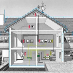
If you live in an old private house or "Khrushchev", then it is likely that the type of grounding system of your home is TN-C. In an apartment building with a PEN conductor (see Fig. 1), its connection is made floor-by-floor in common panels.

If the PEN conductor or the contact in the switchboard breaks, and the phase does not turn off, and the electrical installation of the apartment remains energized, while the protective conductor will not work. In fact, when you touch parts of the equipment that are under voltage, a person will be exposed to electric current and the protection will not work.
In a private house, a similar phenomenon can be observed with a combined PEN conductor. The difference is that a private house may not have floorboards, but have one opening panel.
In order to connect all equipment, including protective contacts in sockets, to the grounding system, it is necessary to transfer the TN-C grounding to TN-C-S, that is, to divide the PEN conductor into two independent wires PE and N.
In addition to the PUE, the requirement to separate the combined PEN conductor at the input to the electrical installations of residential and public buildings, commercial enterprises, medical institutions, is containedGOST R 50571.1-2009 (p. 312.2.1).
How to split
In residential buildings: private houses, cottages and summer cottages, this must be done in the introductory metering panels to the meter, and in apartment buildings and other buildings this can be done in the ASU.
After the conductor is divided into N and PE in the PEN lead-in shield, it is forbidden to combine them further in another place of the electrical installation in the course of energy distribution. This requirement is enshrined in paragraph 1.7.131 of the EMP (see Chapter 1.7).
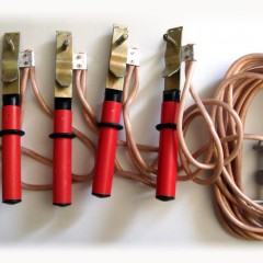
The requirements of the PUE also determine that when installing in the place of separation of the PEN conductor into zero protective and zero working wires, it is necessary to provide separate clamps or busbars for conductors interconnected. The PEN conductor of the supply line must be connected to the terminal or Gzsh (trip bus, fig. 2) or zero protective conductor bus.

If there is no switching device at the input or circuit breaker, then using the trip bus loses its meaning, as it creates unnecessary bolted connections where contact may deteriorate.
Thus, it is necessary to have two buses to separate the conductor. One bus will need to be used to connect zero protective wires, the second - for zero workers.
During installation, both tires can be interconnected using a cable jumper. The lead-in combined PEN conductor is connected first to the PE bus, and then a jumper to the N bus is withdrawn from this bus.
In accordance with the requirements of the PUE (p 1.7.61), when using the TN system, it is required to re-ground the PE- and PEN-conductors at the input to the electrical installations of buildings, as well as in other accessible places, using primarily natural grounding. Resistance of a grounding conductor of repeated grounding is not standardized.
If there are no natural grounding conductors, then artificial grounding and connects to the PE bus to which the PEN conductor is already connected.
With single-phase and three-phase input, the principle of separation of the conductor is the same. The difference is that in a single-phase power supply system there is one input phase wire, and in a three-phase system there are three phase wires.
In new apartments with the TN-C-S grounding system, the separation of the combined conductor into zero working and zero protective is carried out in the main switchboard. Two wires are already going from it separately to the floor board and to the apartments, as shown in the diagram below:

Finally, we recommend watching useful videos on the topic:
That's all I wanted to tell you about where the separation of the PEN conductor into PE and N should be performed according to the rules of the EMP. Once again, we duplicate the answer, so that you probably remember: in private houses, the wire must be shared to the counter in front of the opening switching device, and in apartments this is done in the main switchboard.
It will be useful to read:


but how is all this and the meter comes in how it comes in and how it goes out in 3 phases
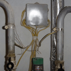
Hello. He climbed into the floor shield to get rid of the charring twists. The picture is as follows: 4 cables pass through, 2 nuts pass through. From one 4 turquoise wires L to ouzo apartments, from another 1 thick yellow to the ground terminal of the shield itself. further, the blue wire welded into the shield from it is connected to N ouzo and then to the counter, and the yellow-green one is to the “earth” one. The house has electric stoves. Uzo replaced the “energy meter” with ABB difavtomat. In my opinion, the TN-C-S system.
Photo attached. Is the splitting correct and why is it in the floor shield?
Next photo
and last
I live in a former hostel (now an apartment building). There are 4 rooms in the block. Power supply from three rooms is laid through my walls and ceiling. Wiring has not changed for 47 years. I was shocked by walls and chandeliers. Please tell me in which section of the rules it is said that each room should be connected to the shield through common areas.
But there is an electric stove in Soviet houses already with a grounding contact, but on the floor board you can see that there is a PEN conductor, and you suggest not connecting the grounding conductor when the wiring is already done, like an apartment board where selectivity is observed, everything is scattered according to consumption groups and separate Is the cable laid on an electric stove?
Good afternoon ! two wires without insulation old aluminum fit into a private house. to get grounding? It is necessary to take the neutral wire and take the bus from it into which to connect all the sockets, and connect the neutral wire from the sockets to the same zero suitable wire to the house only through the input machine, right? I understand correctly that the zero wire is divided into two branches, one is the earth and the second is already through the introductory to ouzo and then has its own zero bus to which all the sockets will come?