How to make grounding in the garage

Why do you need a ground loop
The fact is that most often garages are made of metal with not very good waterproofing, as a result of which there is increased humidity inside the room. At the same time, motorists use a powerful electric tool when repairing a machine - a welding machine, compressor, heaters, etc. All these electrical appliances must be grounded otherwise. leakage current on the case, and especially if the work takes place in a humid environment, you may become a victim of electric shock. In the best case, everything can end with an injury that you will remember for a lifetime. To once again not endanger your life, it is recommended to do the grounding in the garage with your own hands, spending a little time and money on this. Below we will provide simple instructions on how to properly ground the ground loop and which circuits are best not to use.
Existing systems
So, first, briefly consider how you can make the grounding of the garage yourself. There are several systems that are used today.
- TN-C. In this case, a single-phase or three-phase conductor and a PEN conductor are connected to the input shield, combining the functions of the working neutral and protective neutral conductors. Combining a conductor in one means neutral grounding. The disadvantage of this scheme is that when the combined wire breaks, the phase goes to all grounded electrical appliances. As a result, 220 volts will flow on all your metal fixtures and power tools. One touch and the consequences can be fatal, so we do not recommend doing this option of protection on our own. Currently, the TN-C system is prohibited from being used in new construction, as well as in single-phase and direct current circuits, however, there are assumptions regarding the use of this system on branches from overhead lines. According to the PUE (p 1.7.132, Chapter 1.7) TN-C system is allowed on branches from overhead lines with voltage up to 1 kV to single-phase consumers of electricity.

- TN-S. A more reliable grounding of the garage, however, it is unlikely to meet it in reality, because for this, the cooperative must stretch to consumers a separate N and PE wire from the substation to its own ASU.It is clear that doing this is not profitable, so we discard such a grounding circuit.

- TN-C-S. One of the safest systems, which is presented as follows: from the substation to the ASU of the cooperative, the combined PEN wire is extended and re-grounding is organized. Already from the ASU to the consumers there is a five-wire cable: 3 phases, zero and ground. Modern developers use this particular circuit for protecting electrical wiring at 380 volts, but owners of old garages will likely have to pay for the modernization of the wiring themselves. It is clear that motorists will not always agree to this either.

- TT. Well, the last garage grounding scheme is to make an individual circuit of several metal electrodes dug in the ground near the garage. As you know, this is the easiest and cheapest way to protect electrical wiring, which we will talk about now.

Below we will consider one of the options for installing grounding in the garage with our own hands. The instruction with photo examples will help you independently make a PE circuit with minimal time and money.
Connection Instructions
So, to begin with, we will analyze the scheme of the correct grounding contour of the garage room.
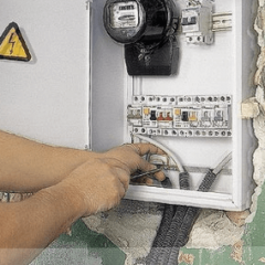
In the introductory shield connect an RCDwhich protects the wiring when leakage currents are detected. The residual current device is a very good helper to the grounding circuit, as in the event of an emergency, instantly turns off the power at the input.
As for the 220V garage ground circuit itself, it can be made either as a triangle or as a straight line, as shown below. Some electricians recommend making a T-shaped protection circuit - drive 2 electrodes in the corners from the front of the room and dig 2 electrodes into the inspection hole. All 4 iron earthing switches are interconnected and connected to the corresponding bus in the shield.

Electrodes can be represented by corners of metal, with a length of 2 to 2.5 meters. The size of the corner should be at least 50 * 50 mm. If you decide to use a metal pipe in order to do the grounding of the garage with your own hands, its diameter should be at least 32 mm and the wall thickness over 3.5 mm.
Well, the last element of the circuit is a flexible wire connecting the underground structure to the grounding bus. It is recommended to use a copper wire with a cross section of at least 6 mm.sq. or aluminum with a cross section over 16 mm.kv.
Having prepared all the materials, you can proceed to the assembly of the contour. The first step is to dig the electrodes into the soil. To do this, prepare small pits, 50 cm deep, according to the selected scheme, and dig trenches between them to connect the grounding armature. The most suitable distance between the electrodes is 1.2 meters. Having dug pits according to the garage grounding scheme, you can proceed to drive a corner into the ground. To do this, it is recommended to grind its lower end in advance with a grinder, and then hammer the electrode with a sledgehammer so that it enters to the end (the upper end should be half a meter below the earth's surface).

The driven corners are interconnected by a metal strip with a width of at least 4 cm and a thickness of at least 5 mm. It is recommended to connect the elements of the circuit by welding, having previously cleaned the metal to a shine.
For the convenience of connecting the wire to the corner, it is recommended to weld a bolt or a special terminal, as shown in the photo below.
Last but not least, a three-wire wire extends from the 220 Volt shield through the garage and is connected with grounding to outlets and lamps. You can clearly see the whole process in the video tutorials below, which we strongly recommend that you familiarize yourself with.
Here, according to such instructions, you can easily do the grounding of the garage with your own hands. As you can see, everything is quite simple and does not take much time.If the garage is located on the territory of the house, then it is not necessary to make an individual protective circuit. It will be more correct initially make the grounding of a private houseand then let the three-wire wire from the home shield to the garage.
It will be interesting to read: