Innovation in the field of surge protection - ONS device
The modern market is extremely saturated with a variety of models of protection devices, in which the classical approaches are implemented: either quick load shedding during overvoltage, with one or another delay (to avoid false positives from permissible interference), or stabilization by classic autotransformat
Development Overview
The model of a synchronous voltage limiter is designed and assembled just for low-power equipment requiring automatic power recovery without much delay. Experimental

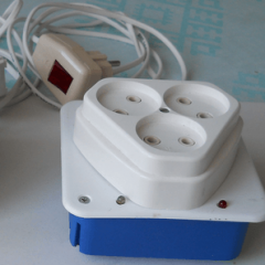
The voltage limiter is designed for power up to 250 watts. It is assembled based on standard distribution
- The possibility of a stationary connection in the power circuit, that is, turning on the power to the load with an inrush current (for switching power supplies) and voltage limitation, or turning off the power when there is excessive overvoltage in the network.
- The instantaneous response of the limiter in a wide range of impulse and spasmodic overvoltages, depending only on the frequency properties of the controls and ballast (up to about 3 MHz - for ordinary elements of widespread use).
- The ability to test in operating mode for maximum voltage limitation (ballast check) and load shedding (via micro buttons).
- Instant load shedding, dependent only on the relay response time (several ms).
- Automatic restoration of the power circuit with a delay of several seconds, provided that the voltage drops to an acceptable level (less than 250 V).
It should be noted that in connection with the characteristics of the load, its purpose, two modifications of the ONS are advisable - with automatic power recovery and only manual recovery. The device of the second modification of the limiter is much simpler, because instead of the relay and its associated elements, a typical, widespread thermo-automat (breaker) is used, modernized
In a minimal version of the design, the ballast radiator is cooled convectively, through the holes in the box (protected by a mesh). To provide greater protection power (heat dissipation), you can use an additional box in which to place a cooler with a current transformer and a thermal breaker
What is the significant advantage of ONS?
In a previous article, the developer has already noted that all consumers in the network are 230 V, 50/60 Hz (rated voltage of a single-phase network according to the new GOST, with a tolerance of +/- 10%), with switching power supplies (with their own stabilization) require a special approach to overvoltage protection. All of them need not just protection against an increased level, but protection against a wide range of surge and surge surges. The modern market is extremely saturated with filters and volt-automata (voltage relays), which include protection elements from impulse noise in the microsecond range. As for longer pulses and surges, jumps, it should be noted that these devices have a certain smoothing (filtering) in front of the sensitive element of the machine (so as not to annoy the owners with frequent operation). That is, they pass some part of impulses. As for the setpoint for operation, it should not be higher than 250 volts. Many “voltage relays" have an external setpoint adjustment, but this should be considered a drawback rather than a virtue. It was introduced just in order not to annoy with frequent shutdowns. But, a voltage of more than 250 volts is very dangerous for any electronic equipment.
As already mentioned in the previous article, it is not profitable for all Manufacturers to provide a large "margin of safety" in voltage for their products. Thus, the entire mass of passive filtering and relay protection devices is suitable only for voltage-stable and disturbance networks, that is, it is designed for rare, accidental overvoltage (during a thunderstorm or network accident). Many of them nevertheless "drive" the owners to "white-hot", to a decisive replacement with a stabilizer. However, modern stabilizers, although they look like perfect devices (including advertising characteristics, especially for a simple buyer), still have a number of significant drawbacks that can only be identified by appropriate engineering testing in a special laboratory. On the Internet there are very few articles on this subject, and they contain only a check of the contents and limiting stationary modes.
What is the main, fundamental difference between the new approach? It consists of the following:
- a synchronous limiter (ONS) monitors each half-wave of voltage and synchronously “cuts” its amplitude to an acceptable level, - based on the allowable effective voltage of less than 250 volts;
- the size of the cut-off part is determined only by the boundary voltage of the ballast transistor and an appropriate limitation of heat generation - for a stable network it can be extremely large, for example, up to 100 volts (then the ballast will cut off pulses of this magnitude without disconnecting the load);
- the entire spectrum of pulses is cut off, depending only on the frequency properties of the ballast and its controls;
- the disadvantage of ballast heat dissipation is not as large as it seems due to the fact that they stand out impulses, the duty cycle of which proportionally reduces the allocated power, for example, in the range of 245 - 250 volts of the output voltage at an input voltage of 245 - 275, the maximum heat generation is approximately six times less than with continuous voltage (the duty cycle is calculated by the sine angles at the boundary of the sine wave cut).
With loads of more than 0.5 kW in a network with frequent voltage surges, it is necessary to equip a synchronous limiter with a fan (cooler), which is advisable to be powered from a miniature current transformer (based on a step-down transformer). Starting with a power of 1–2 kW, it is advisable to use the tandem - “STAB - ONS” - to effectively combine the properties of these devices. The stabilizer provides static mode, and ONS dynamic and active-filter
It should be noted that the use of modern autotransformat
Developer tip
The source of increased voltage should not be LATR, but a conventional step-down transformer with several secondary windings and leads from the primary, so that when the secondary windings are phase-connected with the primary and using certain primary leads, a high voltage can be obtained, for example, up to 270- 275 volts. This voltage must be supplied to the control electronic part of the protection device through a 10-20 kOhm variable resistor. The consumption of control electronics is usually (and should be) no more than 10-15 mA. And the power part must be connected directly to the network, taking into account the phase. With this power scheme, you can more smoothly and accurately set the voltage and form an ideal jump by closing the entire variable resistor or additional.
It will be interesting to read: