9 circuits for correctly connecting a voltage relay
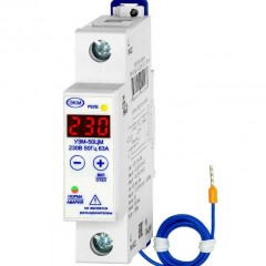
So, the simplest wiring diagram from the opening circuit breaker in the apartment to the voltage monitoring relay is as follows:
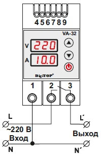
In this case, the network is single-phase (220 Volts) and the load is not more than 7 kW, so there is no need to connect magnetic switch or contactor to din rail. If the load is more than 7 kW, it is recommended to connect through the starter, as shown in the second PH-113 relay connection diagram: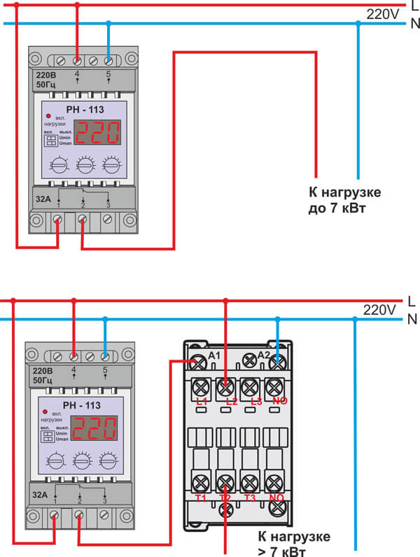
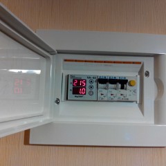
Immediately draw your attention to the fact that in addition to surge protection devices In the switchboard there must be an RCD or a difavtomat to protect the inhabitants of the house from leakage currents that can cause electric shock. The schematic diagram of connecting a voltage relay and an RCD (or a differential machine) looks something like this: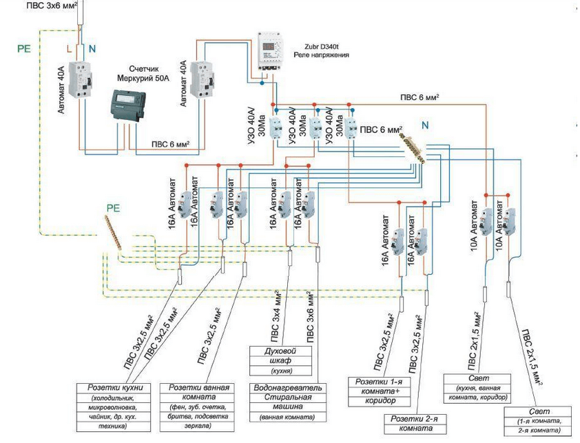
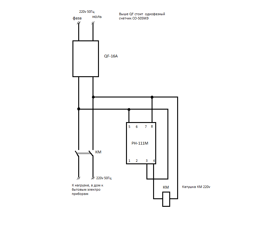
If you have a three-phase 380 Volt network in your private house, you can connect the protective device according to one of two schemes:
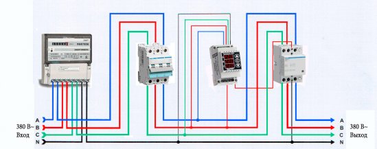
The first is recommended to be used if there are no three-phase consumers in the house — a powerful electric stove or a 380 V boiler. If you use 3-phase electric motors, you must protect them with an appropriate voltage relay, for example, RNPP-311 or RKN 3-14 -08, schemes of which we provide you with: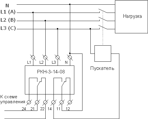
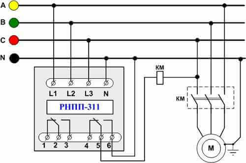
In addition, we recommend that you familiarize yourself with video tutorials in which the entire installation process is clearly explained:
As you can see, in both versions there is an additional magnetic starter, which allows switching high loads (over 7 kW). In addition, the starter allows you to remotely control the protection, which makes this voltage relay connection scheme very convenient!



In Fig. 3, as an example, the input and all wiring are made by PVA. Is it a joke or wrecking ???
rather, just taken as an example. the article is not about that
What's wrong with PVSka ???
The fact that it is not intended for wiring. This is a wire. Stationary wiring is done by CABLES !!!
Question. And if there are 3-phase and single-phase devices in the building (house)? Use different power “branches” with separate monitoring relays on each of them?
In the figure that Sergey indicated, after the electric meter, power should come to the upper contacts of the machine.
And the shemka is not right. Zeros after different RCDs should not be combined.
Well, how right ????
Each group on the RCD has its zeros. Plus, the RCD rating is chosen incorrectly, it should not be equal in this case to the Introductory machine. Either more of the input automaton, or the total automata of the RCD group are less than the rated current of the RCD
I'm electric. He made wiring in the house and put a three-phase voltage relay through the contactor, how much should I evaluate my work?
It's simple - call your competitors and find out the cost of doing the job as a client. It all depends on the region.